Help with alternator wiring

Stephen Newell

Well-known Member
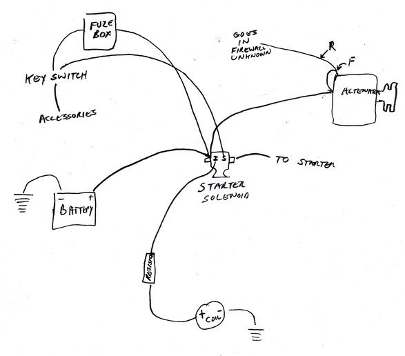
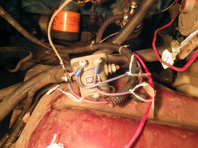
I've got an old jeep which doesn't have a voltage regulator with the alternator and I keep burning up gauges. What is there now is a Y which connects the fuse box, alternator and battery.
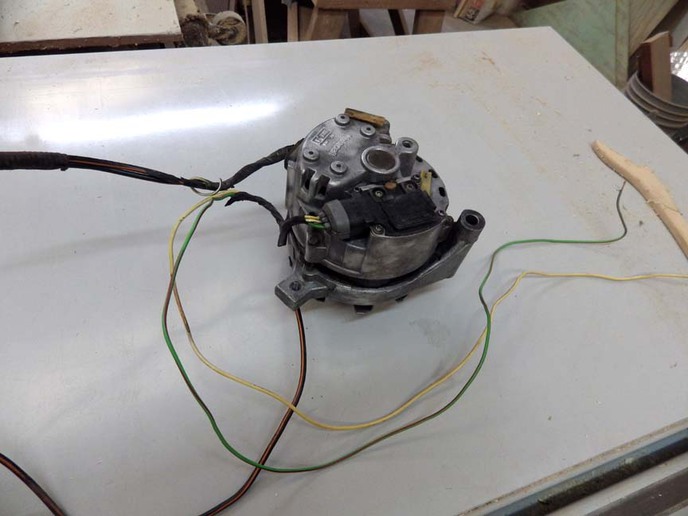
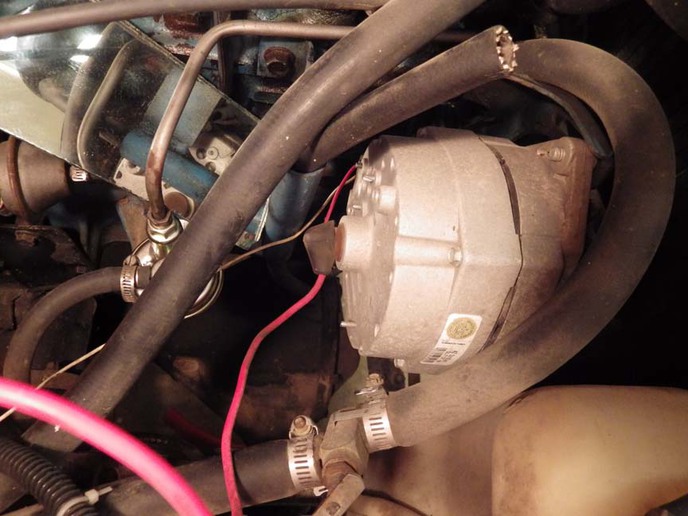
I know most of the problem is with aftermarket gauges but I thought I would replace the alternator. I've got one off a 86 ford tempo which I know was working when I retired the car and it has a self contained voltage regulator.

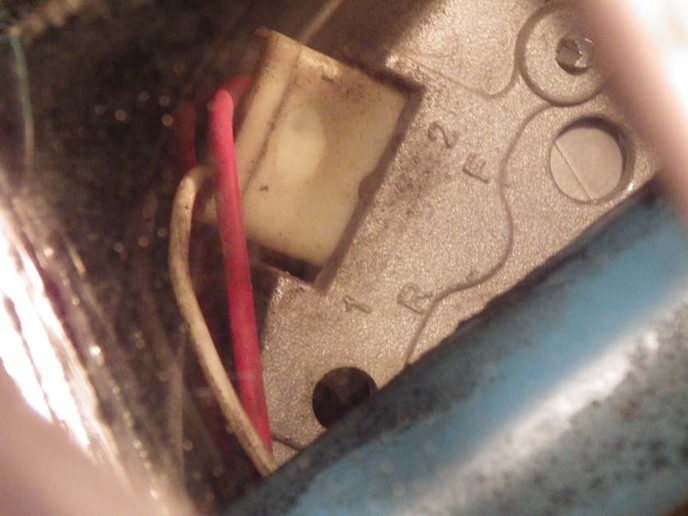
What I'm not understanding is I hooked the alternator to the battery and the A terminal and the I terminal as well as the stator wire on the regulator have less than .2 volts on them. According to the wiring diagram I was suppose to go to an indicator light and then to the start switch. At that voltage there isn't enough power to engage the start solenoid.
 
NO WAY is "I" going to supply power to your starter switch.

You should have left the wiring to the starter switch as it was, as there was need need to change it to install an alternator.

Try this diagram... it does NOT show the wiring to the starter solenoid, you can put that back as it was.

<img src = "http://www.gondtc.com/~blweltin/Bob/SimpleFordAlternatorCircuit2.jpg">
 
Thanks Bob, I haven't changed anything yet. I'm still trying to get an understanding and the internet isn't a lot of help. There are so many different variations and applications it's more confusion than help. The replacement alternator is shown in the picture and there is no F on it. The A wire is the loose white wire and the I is the loose green wire with the red stripe. The S wire went back to the stator on the alternator. This is the way it came off the car and none of the wires have 12V on them when the alternator is connected to the battery.

The way the existing alternator is wired is the power supply for the fuse box is wired to the power supply side of the starter solenoid. This wire is what I was hoping to regulate. Someone suggested I just put a resister on that line but I'm afraid since I'm burning gauges within days there is some issue with the alternator too.
a228134.jpg
 
IGNORE my previous post, as I based it on a different version of a Ford alternator system!

"The way the existing alternator is wired is the power supply for the fuse box is wired to the power supply side of the starter solenoid. This wire is what I was hoping to regulate."

Yes, that is typical, and when you get an alternator/VR operating correctly (as you know) it will regulate the battery AND system voltage.

We can help you with this... could you post a drawing of how the system is wired now, and a photo of the alternator in use now so we can see why it isn't regulating the alternator's output voltage.
 
Yellow wire is hot all the time to sense voltage. Green wire comes off ignition switch to excite alternator when key is on. white wire goes to white wire on output plug. Cnat see it but that looks like where it is going now. hth jstpa
 

If it's internal regulator, you only need two wires; 12v off the ignition switch to the small wire terminal on the alternator. Then the 10 gauge wire that is the output and you decide where you want to connect that to the battery positive.

The small wire is the field power, it goes to one of the brushes, thru the slip ring on the rotor, thru all the rotor windings, and back out thru the other brush, and then to the regulator. The regulator completes the circuit thru the rotor by providing a ground. Understand?

This is know as an "A" type regulator, since the regulator is after everything else. A "B" type is the traditional external regulator that is before the rest of the circuit.

The additional wires are used to power up the charging indicator light. That has 12v coming off the ignition switch when you turn it to 'run'. The 12v goes thru the bulb, down to the stator output, and is grounded there. So the light goes on. When the alternator starts spinning, it generates an opposing 12v current in that stator wire and that is 'pushing' back up toward the light. 2 `12v currents opposing means no current movement thru the bulb, so the light goes out.

If you want an ammeter, you bring the output wire to the + terminal on the back of the gauge. Then from the -, back to the positive battery post. Voltage gauge, tap into a wire that shows voltage with the key in the run position.

An ammeter was what the OEM was, but if it was mine, voltage gauge all the way. You're not running the entire output into the dash and back; lots easier to do the voltage gauge.
 
There is one wire so far I can't find where it goes. It's the white wire that goes from the R terminal on the alternator and disappears into the firewall somewhere. I will keep looking but this is what I have so far.
a228154.jpg

a228156.jpg

a228157.jpg

a228159.jpg
 

If there really is a jumper from the output terminal to the field terminal, you don't need the white wire, since that probably is the wire to power up the indicator lamp in the dash. Once you get this working, test the white for voltage; should be 12v.

I'm surprised about the jumper, because that will draw about 5 amps from the battery. That's why it's usually a wire off the ignition switch that supplies that current; it's disconnected with the key off. Does your current setup kill the battery in a day? It should.
 
The current setup has been there for sixteen years and hasn't been a problem with the battery. What I've been having trouble with is the gauges. There is a fuel and temperature gauge in the speedometer cluster which I've replaced twice in the last few months and need to again. Even the voltmeter which goes to 16 volts burned up. The only reason I replaced that one is it had a plastic ring next to the glass on the inside that disintegrated.

The white wire was for a generator light.

As stated in my initial post when the new alternator is wired to the battery neither terminal A or I on the voltage regulator has any real power. I have to wonder if it's gone bad sitting in the car for years.
 

Take it to Autozone, they have an alternator test rig and can tell you if it's toast. If you're burning up stuff, it's a voltage regulator problem, not an alternator. The only reason to have the regulator is to keep the voltage below 15 volts. Alternator has to be working to fry stuff.
 
I'm sorry, I read it but I didn't exactly understand it. The yellow wire isn't hot at all. This is what prompted me to come here. I was expecting both the yellow and green wires to be hot and neither of them were. I don't have it wired into the jeep yet though, I was testing it on the bench.
 
Stephen,Was your Jeep a 6 volt system originally,if it was you need a 12 volt to 6 volt resistor for the interments to work right.
 

We sell tractor parts! We have the parts you need to repair your tractor - the right parts. Our low prices and years of research make us your best choice when you need parts. Shop Online Today.

Back
Top