Motor Wiring

Terry G

Member
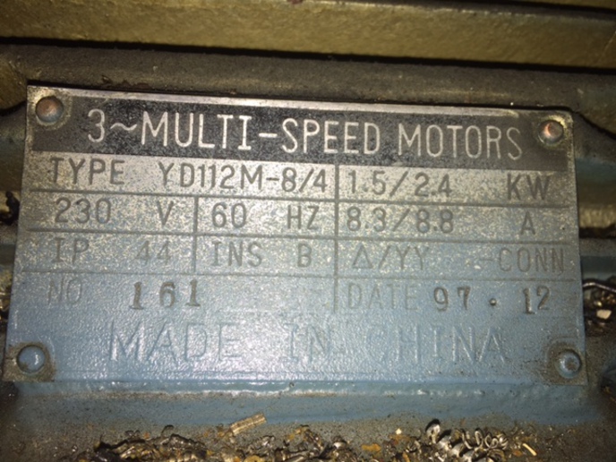
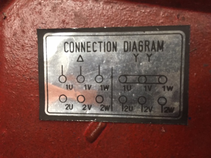
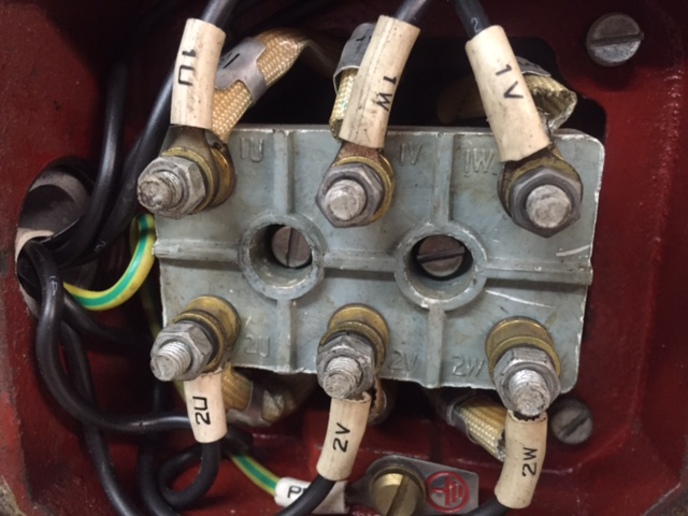
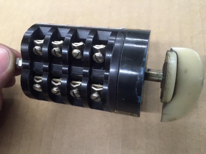
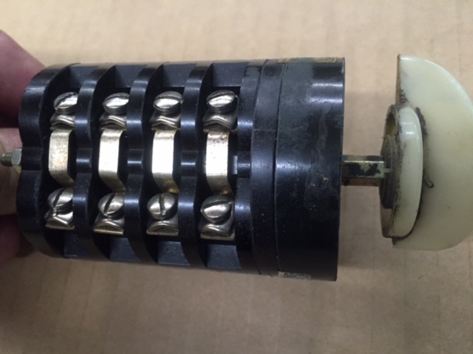
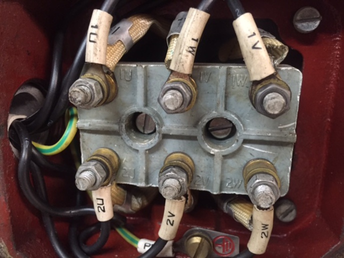
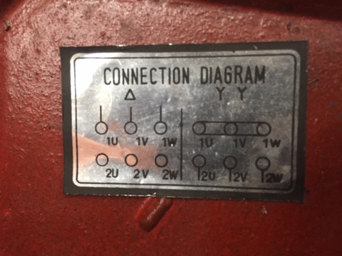
I have this 230V 3 Phase motor that is wired like the left side of picture #2. It has a speed selector switch with 3 wires from each side going to the motor connections (picture #3). What is the diagram on the right side of picture #2. Is this another way to wire it and what would that give me. This is on a metal lathe and I am going to run it with a VFD. Just want to make sure the motor is wired right for the VFD. Thanks for any help.
a222948.jpg

a222949.jpg

a222950.jpg
 
(reply to post at 12:58:21 04/07/16)
High speed mode has reduced the number of poles . The motor's cooling fan will work better with the motor in the high speed mode.
Use the gearbox to reduce speed and keep the motor up near rated rpms.
 
So to wire it for wye would I tie 1U, 1V and 1W together and run the 3 power wires to 2U, 2V, and 2W? And I guess this would be just a single speed then? I may not need to do this but would like to have some understanding of it any way.
 
There should be a metal "strip" that bolts to the motor studs? Usually wired delta but I'd have a qualified person look at the whole situation. We don't cost that much...
 
In Y you have two fields in series with a voltage drop of 110v on each field. on Delta you have 220v drop on each field. I would try it the way its wired now, in delta
 

Could be this configuration ?

https://www.google.ca/search?q=Y+delta+two+speed+three+phase+connection&rlz=1C1KMZB_enCA649CA665&espv=2&biw=1280&bih=675&tbm=isch&tbo=u&source=univ&sa=X&ved=0ahUKEwi5rseK4v3LAhWCiRoKHQTgAscQsAQIGg#tbm=isch&q=Y+delta+two+speed+three+phase+six+terminals&imgrc=vgty8xcDrRt34M%3A
 
we would have to see where the heavy flat white wires go under the block. I know this is confusing, an electrician should involved before you add any more jumpers. IMHO
 
A little more information. There are no jumpers on the connection block on the motor. I took the speed selector switch off and traced the wires on it. It is configured so on speed 1 power is applied to 2U, 2V, 2W and (1U, 1V, 1W) are jumpered together in the speed switch just like the diagram on the right. On speed 2 power is applied to 1U, 1V and 1W and nothing is connected to 2U, 2V and 2W just like the diagram on the left. I am assuming the high speed is speed 2 as the switch was not labeled low and high, does that look right? Thanks for all of your replies, there's so much good information on this forum.
a223004.jpg

a223005.jpg

a223006.jpg

a223007.jpg
 

We sell tractor parts! We have the parts you need to repair your tractor - the right parts. Our low prices and years of research make us your best choice when you need parts. Shop Online Today.

Back
Top