guido
Well-known Member
Hello,
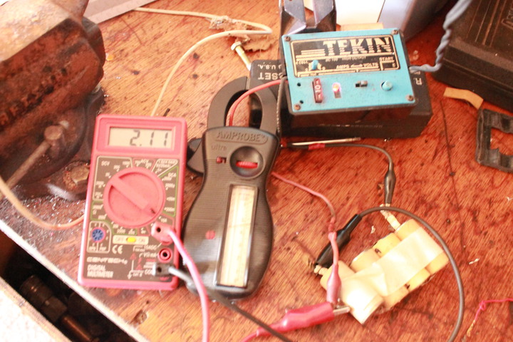
This is the amprobe that I used to measure DC Amps while charging two 2200 MAH Lithium batteries in parallel. Charging at about 1 amp at 3.87 volts and climbing. The amprobe was set at the 6 amp AC scale. It can measure AC amps up to 300, AC volts up to 600. It also has a ohms scale up to 1000 ohms. Old unit but still pretty accurate.
Can someone explain to me why it is working?
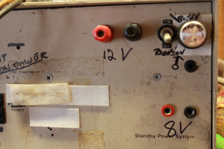
My home made charger is not that sophisticated. I'm pretty sure it is more like a linear output then a pulsating current,
Guido.
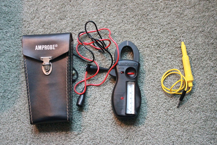
This is the amprobe that I used to measure DC Amps while charging two 2200 MAH Lithium batteries in parallel. Charging at about 1 amp at 3.87 volts and climbing. The amprobe was set at the 6 amp AC scale. It can measure AC amps up to 300, AC volts up to 600. It also has a ohms scale up to 1000 ohms. Old unit but still pretty accurate.
Can someone explain to me why it is working?
My home made charger is not that sophisticated. I'm pretty sure it is more like a linear output then a pulsating current,
Guido.