Lectrical Help

Anonymous-0

Well-known Member
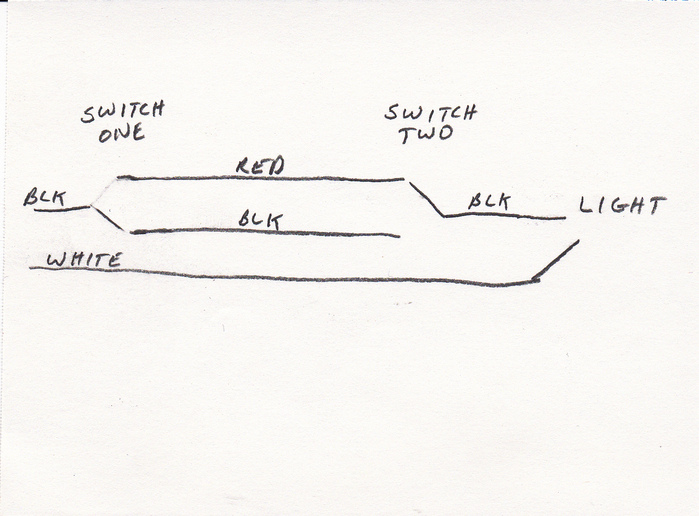
Went to a friends house he wanted me to help put in a new light over his sink. The old one was wired with 2-way switches. Red white and black wires at the switch, with just black and white at the fixture. We noticed that even with the switches in "off" position We are reading 10 volts at the fixture. No matter which way we position the switches or unhook wires we still read some amount of low voltage. We were going to cap off one of the switches and just make the circuit -- ON/OFF with one of the switches but we kept noticing 10 volts showing up even in off position. This is red white black with no green ground any where.Thanks.
 
I think if two wires run parallel to each other there will be some voltage present in the supposedly dead wire. Check it with a test light or a wiggy to see if there is any real power there.
 
Were you using a digital meter? They are so sensitive that they read induced voltages in conductors. Often the reading will be as high as 60 volts. If a digital meter, my guess is that there is really no problem.
 
It is normal for a digital multimeter to read voltage on an open circuit. The input impedance is high enough that normal 60 Hz noise will register on the meter as a significant voltage.
 
That is what I was taught to call the transformer effect. Any time you have wires running close to each other you can see ghost voltage due to inter element capacitance and if you use a digital meter it is a lot worse so I would say you have no problem. If you have a flash light bulb try it in that line and I bet you will not get it to light up
 
You were likely measuring neutral voltage vs. true earth potential.
If the line switch is open, the neutral voltage will appear on the load side of the switch through the lamp.
This all goes back to our dozens of previous discussions about the difference between neutral and ground.
 
We were using a two wire orange light test probe as well as a High Quality Fluke ANALOG test probe. It was suggested to me that the low volt in the line was used to power the lighted wall switches you can see in the dark??? how does that work?? The guy that wired the house was a retired Electrical engineer with too much time on his hands, so many things are overkill. (IE) Two way switches in closets that also affect kitchen outlets ,permanent electric wall clocks in every room,Electric furnace,junction boxes to no where, ETC. ETC>.. This was not to the earth ground test this was 10V from the the black to the white wire at the bulb outlet 14-2 . A real Rube Goldberg original. Probably very correct for 1974 standards.Thank-you for your help and ideas.
 
If the light was wired with two switches they should have been wired with three way switches. A three way switch just switches the hot lead from one runner wire to the other. Both switches have to be switched to the same wire to make the connection. You can cap off one switch however you have to find out which one has the power coming into it and wire from that one. It might be easier to put it back with two three way switches.
a100191.jpg
 
If you have lighted switches, there is a small amount of current traveling through the wires when the switch is off. If there's at least one light bulb in the circuit, then you'll see no voltage because the load of the bulb effectively grounds the switched line. But if you try to read the voltage without any bulbs installed, then you will indeed see significant voltage because the input impedance of the meter is too high to ground the circuit.

Rule number one: whenever possible, always measure voltage when there is a load on the circuit. This is true whether you're looking for an open or a short. You will get very misleading results if you try to measure voltage on circuit that has no load.
 
Right inside the main panel where the Neutral and Ground Busses are bonded together, the voltage between the two (effectively across a short circuit) is near ZERO. HOWEVER as you get further from the panel and Neutrals and Grounds and Hots are all in paralell theres like a capacitor (capacitor effect) with possible voltage between two ends of a capacitor.

Similar, the voltage from Neutral to mother earth is near zero at the panel since the grounding electrode conductor (No 4 bare copper wire) is connected to the Neutral which leads to a grounding electrode (like a driven rod into earth). HOWEVER as you get downstream with Neutrals in paralell with hot conductors mutual inductance (transformer effect) plus the capacitance referred to above can all yield a Neutral voltage higher then mother earth.

Also old fashioned analog meters and newer digital meters yield different results subject to their input impedance and how they work, I love my old Simpson 260 analog in these applications. An "ideal" voltmeter has INFINITE resistance so it doesnt draw current and affect the true voltage between the test points.

Sure the 3 way switch (two single pole double throw switches) is wirede correct???

John T
 
There is an old style 3way switch setup that can cause that effect?

I've got it in my house, 1930s setup.

When I had a new breaker box put in, my stairs lights were glowing at night, told the electrician the next day, and he said oh, the old style. He flipped the neutral and hot wires, and took care of it. He said those old type, makes a difference which side gets hot, but didnt elaborate.

Paul
 
For over 50 years I know of ONLY ONE way to wire them using two SINGLE POLE DOUBLE THROW SWITCHES. Each THROW wires to the other switches THROW (runners),,,One POLE wires to the branch circuits hot voltage SOURCE, The other POLE wires to the LOAD. Maybe there was an OLD way before I first learned how to wire them or different then single pole double throw switch use????

Fun chat, wish I knew an old versus a new way???

John T
 
No it is just that a wiggy is ready to go no knobs, no on/ off switch, it either tells you if you are going to get rapped or go ahead no power. By the time the original poster and his friend got done talking about the 10 volts on the Fluke meter a real electrician would have the new fixture already installed. Almost any troubleshooting can be done with a wiggy containing a built in continuity light. Thats all you need.KISS. This is not the first time I have heard of a meter confusing a homeowner looking to change out a bad switch etc.
 
You are reading phantom voltage.....voltage induced into the circuit from other circuits......it is static electricity basically.
 
I hate to be a nitpicker, Sparky, but an induced voltage is not the same thing as static electricity. You're talking about the effects of a magnetic versus electric field. Not the same at all.
 
(quoted from post at 06:29:10 02/04/13)

Fun chat, wish I knew an old versus a new way???

John T

There is an old way. It was used to run a yard light on the pole between the house and barn. It used one less wire and powered from both the house and the barn.
Not a very safe because if one was going to work on the light and turned off the power at one end he didn't realize it was still hot from the other end.

I think is was called Chicago Loop.

Not legal today. I can't quite remember how to wire one that way, and don't want to.

Dusty
 
Good discussion. Been there. done that. All of them. Dr. is right. Wiggy, best tester every made. Too sensitive a meter is sure trouble. Unmarked wires(knob and tube) will cause identified problems. Like a bult that faintly glows. When in doubt, draw it out. Plan your work and work your plan. If you can't figure it out get expert help. Somebodies life is at stake. Dave, retired master, contractor and low priced electrician. No more free advice unless the price is right. Simpson meter is second choice since the 60.s
 

We sell tractor parts! We have the parts you need to repair your tractor - the right parts. Our low prices and years of research make us your best choice when you need parts. Shop Online Today.

Back
Top