6 volt sytem with cutout and no field terminal

tvscum

Member
I have a 1926 Gotfredson farm truck. It has an internally ground three bush generator with a cutout and no field terminal:
http://www.yesterdaystractors.com/articles/artint4.htm

The light switch has labels for OFF, DIM, ON.

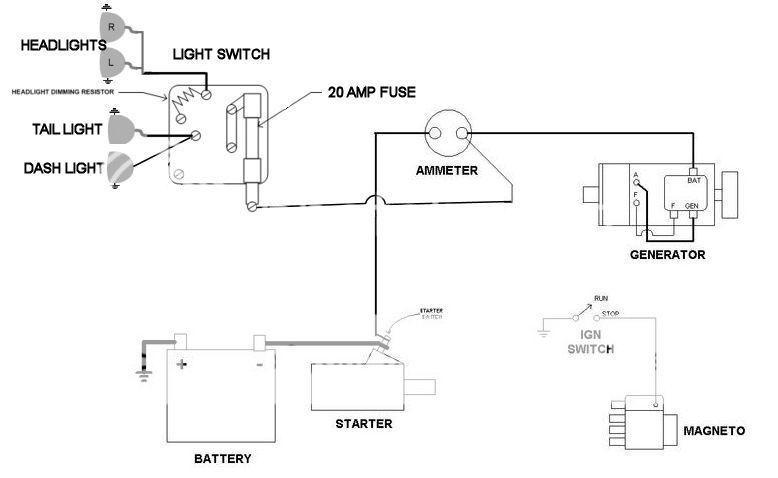
I am a rookie at wiring and I created this draft wiring diagram. With it work?
Gotfredson%20wiring%20diagram_zpsqymxj4vf.jpg
 
But you say there is no field terminal... Yet there is a field on the regulator and gen in the drawing?

If there is a field circuit, the drawing would work.

If there is not a field circuit, then it would wire like the bottom diagram on the link.

Have you ohmed out the function of the resistor in the light switch? If you are sure it functions as drawn,
it is probably right. However, there is a possibility the resistor was originally part of the charging
circuit, as in the top drawing and explained under the resistor light switch heading.

I haven't seen a low beam actuated by a resistor, but anything is possible that far back. If there is any
evidence that it had dual element headlamps, or 3 wires going to the headlamp (high circuit, low circuit,
ground), then I would recheck the function of the headlight switch.
 
(quoted from post at 21:28:01 01/17/16) But you say there is no field terminal... Yet there is a field on the regulator and gen in the drawing?

If there is a field circuit, the drawing would work.

If there is not a field circuit, then it would wire like the bottom diagram on the link.

Have you ohmed out the function of the resistor in the light switch? If you are sure it functions as drawn,
it is probably right. However, there is a possibility the resistor was originally part of the charging
circuit, as in the top drawing and explained under the resistor light switch heading.

I haven't seen a low beam actuated by a resistor, but anything is possible that far back. If there is any
evidence that it had dual element headlamps, or 3 wires going to the headlamp (high circuit, low circuit,
ground), then I would recheck the function of the headlight switch.
own an original Farmall SMTA & have the books on it & it does in fact use a resistor to dim the lights. Not 2016 technology.
 
(quoted from post at 18:28:01 01/17/16) But you say there is no field terminal... Yet there is a field on the regulator and gen in the drawing?

If there is a field circuit, the drawing would work.

If there is not a field circuit, then it would wire like the bottom diagram on the link.

Have you ohmed out the function of the resistor in the light switch? If you are sure it functions as drawn,
it is probably right. However, there is a possibility the resistor was originally part of the charging
circuit, as in the top drawing and explained under the resistor light switch heading.

I haven't seen a low beam actuated by a resistor, but anything is possible that far back. If there is any
evidence that it had dual element headlamps, or 3 wires going to the headlamp (high circuit, low circuit,
ground), then I would recheck the function of the headlight switch.

I created that wiring diagram using a combination of ones I found online. That generator field circuit in the diagram may not be correct or it may be an internal circuit. I definitely do not have a field terminal. I think I have this "thermostatically controlled" type (from the link above):


[i:be72a01bd8]"Internal Regulation
If you did not have an F terminal, there is still regulation going on in the generator. The most interesting type uses a thermostatically controlled set of points in parallel to a resistor. These are connected to ground to approximate the function of external regulation. The thermostat heats up by running at a high charge causing the points to open which slows generator output. When it cools down the points close (once again connecting the 3rd brush directly to ground) and generator output increases until it heats up again."[/i:be72a01bd8]

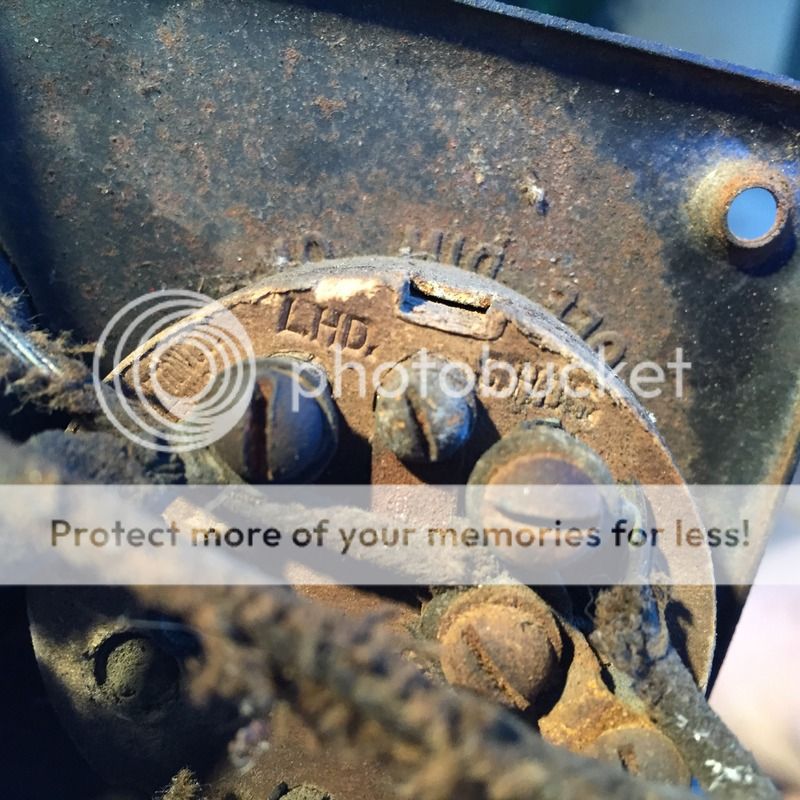
As for the OFF, DIM, ON light switch. There are two leads on the back. One says L.HD. and the other says S.HD (and I assume they correspond to the DIM and ON settings). Any idea what these initials stand for?

Here's a photo:

IMG_2650_zpsxsddkbwt.jpg


At any rate. I hooked up the gauge cluster and it all seems to work fine, including the amp meter and the dash light. I have not hooked up the headlights or the tail lights but it should work. Is that 20 AMP fuse sufficient?
 
The reason I ask about that fuse is, eventually, that single fuse is going to be handling the headlights, the tail lights, and the dash light. I have no idea what amp the stock fuse was.

I also have to hook up a horn but that probably needs to go on a separate circuit and inline fuse, I suppose.

(Like I said.... Rookie)
 

We sell tractor parts! We have the parts you need to repair your tractor - the right parts. Our low prices and years of research make us your best choice when you need parts. Shop Online Today.

Back
Top