Ford 8N Wiring Question / Help

mcewan79

Member
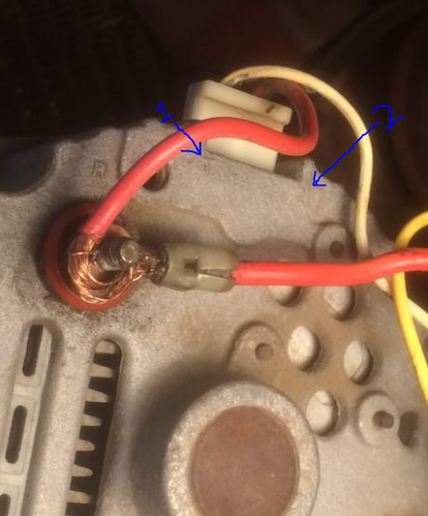
Finally getting around to messing with the electrical on this tractor (trying to figure out why the alternator isn't charging). Runs fine
but not charging. The wiring has me perplexed. I've posted a picture of the set up.

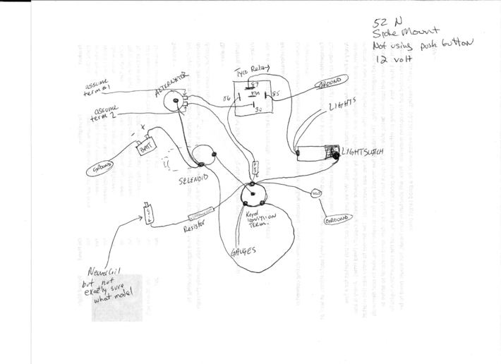
What has me puzzled the most is the relay box, whether its needed (don't really see on any other diagrams) and if its hooked up correctly??

Also curious if I need the regulator, suppose I need to figure out the Coil ohms - if not needed, does it hurt to leave it in there?

If any of you smart fellers want to point me in the right direction, its appreciated!


Thanks!
Matt
a190594.jpg
 
Cannot see you diagram well enough to say. If you have the common Delco 10si here it how it should be done. Wire from the charge stud goes to the amp meter if you have one or the solenoid if not. #2 wire goes right to the charge stud. Then the #1 wire goes to the ignition side of the coil or to the side that is hot when on of the ignition switch. You need a resister or diode in line or you will not be able to shut it off
 
#1 pin on alternator needs momentary voltage to kick start the alternator to begin charging. The relay is an unnecessary, overcomplicated way to supply that start voltage.

Terminals on the relay are 86-85 activating coil. Ground one side and power to other side to activate. 30 is common terminal. 87 is normally open and 87a is normally closed. In off condition there is connection between 30 and 87a. When activated connection switches from 30 to 87.

Power appears to come to the main switch. The ignition output goes to coil(correct) and to activate the unnecessary relay, and to power the light switch. This has the lights current going through the ignition switch which overloads that switch.

The output of light switch goes to lights and to 87 terminal on relay. When relay is activated there is connection from 87 to 30, but no power at 87 until light switch is turned on. You must turn on light switch to start alternator to charge.

Pin #1 on alternator should connect to output of ignition switch. However if connected directly the alternator may feed back to the switch and cause the engine to continue to run when the switch is turned off. Usually a diode or lamp is inserted in this line to prevent feedback.

I'm guessing the relay is a way over complicated way to make the engine shut down when switch is turned off.

Old shows how to rewire alternator

I'd move the power input for the light switch to power connection at main switch or to alternator charge connection at the solenoid.

For safety sake I would get the Ford solenoid and restore the original start switch.

This appears to be a later 8n with side mount distributor. If so check + to – terminals with ohm meter. If 1.5 ohms use the resistor, if 3 ohms eliminate the resistor.
 
Thanks very much for the replies, helps A LOT. That unnecessary complicated relay has wasted a lot of my time! Soundguy you crack me up.

A few more questions, if I haven't worn y'all out already. Kinda making sure I get this at least kinda right.

1. More of a comment, I guess I had the coil connected to the ACC vs. IGN on the keyed switch, surprised it started (so I read). Will fix that.

2. rvirgil - you said move the lights as it would overload the ignition switch. I'm guessing you thought I had both the lights on coil hooked to IGN? Connecting it to the ACC on the keyed switch okay? I might just connect at the selenoid instead. Unless one is better than another?

3. I read online (and not to doubt OLD, as I think most are doing it his way) that its better to wire #2 terminal to the ACC or selenoid junction versus back to the alternator bat post. I was thinking I'd just tie it in at the selenoid. Are any of these any better than others, seems like its all connected to itself somehow anyway?

4. Read its best to hook the voltmeter to the 'coil side of ignition switch' which I assume is the IGN post on the keyed switch (goes to coil). I have it connected to ACC now. Either better than the other?


None of this might make any big difference so hope I'm not wasting your time. Certainly appreciate any advice!


Thanks-
Matt
 
Oh yeah, and whomever wired this and thought 'it must be a great idea if the alternator only would charge when i turned on the lights' LOL Glad I asked and glad y'all are smarter than me!


1. Leave coil connected to ACC. With switch on ACC and IGN should both be hot, with switch off they should be isolated. If this is so, it will eliminate need for diode or lamp in #1 line.

2. Original wiring had a junction block on back side of dash. With that apparently gone I would power the lights from solenoid, same place as ignition switch. Purpose is to keep light current and heat potential away from ignition switch.

3. #2 terminal on alternator is voltage sensing. Regulator is designed to keep this voltage at a predetermined level. With vehicles, long wire runs and junctions can cause voltage drops so this connection is often made at the solenoid. Old tractors, if they have good wiring and connections seldom have this problem so the connection can be conveniently made at output of alternator.

4. Volt meter draws very minimal current. Just be sure it is connected so it is switched off when engine is turned off. Either ACC or IGN should work.

I would replace all wires that are old, stiff, or cracked. I'd also restore the original solenoid and starter button for safety reasons. It would prevent cranking the starter with tractor in gear.

Sounds like you are on your way to getting the mess resolved. Keep us posted on how it turns out.
 
Thanks again! Makes sense. Im pretty confident itll go smooth. And if not, I'll try not to be embarrassed to ask more questions!!


Thanks
Matt
 
Thanks again yall
Everything worked fine, pretty much followed all directions.

One note, i had switched the ign and acc in a previous post, all were hooked to ign which explains why everything was working.

Thx
 
Alright, some follow-up.

Battery is draining when shut off. I figure either an alternator issue (it is charging) or that I just need to put a diode in the line. I detected power at all three alternator terminals with the key turned off. Tractor will turn off, but perhaps still need a diode to prevent battery drain.

Or.. think i need to rebuild the alt?


Thx
 
(quoted from post at 09:41:38 06/17/15) Alright, some follow-up.

Battery is draining when shut off. I figure either an alternator issue (it is charging) or that I just need to put a diode in the line. I detected power at all three alternator terminals with the key turned off. Tractor will turn off, but perhaps still need a diode to prevent battery drain.

Or.. think i need to rebuild the alt?


Thx
retty hard to tell how it is currently wired after all the changes, but hopefully you have coil powered from IGN and nothing on ACC except #1 to alternator. If not, do that. Diode will not cure a drain problem.
 
JMOR

Yes, the coil is running from IGN, not ACC. From ACC I think I also have the lights (switch) the voltmeter hooked in and maybe the #1 wire
from alternator (whichever one is not wired back to the bat bolt on the alternator, and I triple checked I had that hooked up correctly).
Also, I have all this tied into a keyed ignition, not original 8N set up.

If diode won't help, should I rebuild the alternator (is there one specific part, or just buy the standard rebuild kit) or is something
else wrong? I had assumed the test I saw online about checking current at all three alternator terminals was a sound method.

I could sketch out a wiring diagram if that would help, just going off memory due to the rain...


Thx!
 
I would start with determining which of the 3 alternator wires is draining your battery. Using your multimeter, set to amperes or milliamperes, connect it between the battery post & the cable normally connected to that post. It will read the amount of drain in amperes or milliamperes. Next, while watching that meter reading, disconnect the 3 alt wires one at a time and note the change in reading. When you disconnect the one causing the drain, the reading will drop to zero.
 
Alright, have an update. One question and the rest is just FYI (and to potentially help others with similar issues).

To check current (amp draw) I installed the DMM (digital multi meter) inline (between battery cable and battery post, positive side but don't think it matters) and measured on the amp setting using the 10A port. With everything hooked up like normal, there was a draw of 3.5A. When I disconnected the #2 wire (from #2 post to alternator post), the draw dropped to .35A. Leaving that wire disconnected and then removing the #1 wire (#1 post to ACC on keyed switch) the draw dropped to .05A. I would have liked to have seen a 0, but didn't feel like putting the effort into figuring out what was draining the .05, and figure that is really no big deal (if I'm off base, please let me know).

So, here is the question -
Will an alternator rebuild kit fix the issue? Or would it be better off to just go buy a new/reman alternator?

(If I didn't state it earlier, alternator is a Delco 10SI 3 wire, 3 o'clock)

Also, I've attached an image of my current electrical wiring. Much simpler than how it started!

THANKS to everyone for the help!

<image src="http://forums.yesterdaystractors.com/photos/mvphoto22880.jpg"/>
 
Are you sure that you do not have alternator #1 &amp; #2 reversed, i.e., calling or thinking #1 is # 2 &amp; visa versa?
My reason for the question is that power applied to #1 will result in about 3 amps in most of those alternators. Power applied here should be switched power, not full time battery power, as would be the case if #1 were connected to stud on rear of alternator (incorrectly).
 
JMOR

You're a pretty smart feller! So, I don't have the #1/#2 swapped (pic attached, more of just fyi for anyone else reading the post I guess,
or for you to double check in case I'm dumber than I think!). The logic you added helped to get me thinking...

So, previously, I had measured amps, then removed #2 & measured, then #1 and measured (with #2 still removed). So, I went back out and
this time removed #1 first, which took it from 3.5A to .05A. That got me thinking (from your notes) that power must be going to #1. #1
was hooked to the ACC port on the keyed ign switch. Hooked the DMM up to check voltage at there and it was hot, showing same voltage as
battery. So, logic tells me that the keyed switch must be bad. (I suppose if it was darker out I'd notice the lights on the gauges, doh).

Anyway, before I get too excited over here, think I'm right? Or more testing to do?


Thanks!!
a194041.jpg

a194041.jpg
 
(quoted from post at 16:43:46 06/19/15) JMOR

You're a pretty smart feller! So, I don't have the #1/#2 swapped (pic attached, more of just fyi for anyone else reading the post I guess,
or for you to double check in case I'm dumber than I think!). The logic you added helped to get me thinking...

So, previously, I had measured amps, then removed #2 &amp; measured, then #1 and measured (with #2 still removed). So, I went back out and
this time removed #1 first, which took it from 3.5A to .05A. That got me thinking (from your notes) that power must be going to #1. #1
was hooked to the ACC port on the keyed ign switch. Hooked the DMM up to check voltage at there and it was hot, showing same voltage as
battery. So, logic tells me that the keyed switch must be bad. (I suppose if it was darker out I'd notice the lights on the gauges, doh).

Anyway, before I get too excited over here, think I'm right? Or more testing to do?


Thanks!!
a194041.jpg

a194041.jpg
ould be switch, but could be bad VR inside the alt. Pull the alt plug (red &amp; white wires) and measure switch ACC on/off to see if it is switching. Most likely the switch if all wiring is as you say.
 

We sell tractor parts! We have the parts you need to repair your tractor - the right parts. Our low prices and years of research make us your best choice when you need parts. Shop Online Today.

Back
Top