Please educate me on spark

dactura

Member
47' 8N was running rough. After a while I'd had enough and decided to take a look at the wires to the plugs and distributor. One of the connecting leads was off the distributor - so I re-inserted it and it ran much better.

A hot day - I decided to drag a log back to the house. I progressively had a difficult time I stopped and attempted to start it. I noticed that with all the cranking just as I released the starter button it attempted to fire. This made me recall an earlier post that if the coil is starved of juice it will not output enough to give spark. I was able to start it by rolling it down the hill and popping the clutch in 4th gear and it ran fine.

I parked it under a tree for several hours while I finished the job with my MF30. I decided it was likely the coil - since that is the culprit of most of this tractors mischievous behavior. I remember reading that a heated coil will crap out... but after cooling down it will perform normally.

When the tractor was "room temperature" - it started just fine. I have decided I need to replace the coil.

Here's my questions:

What causes a coil to go bad?
How could my loose wire problem contribute to this?
What's the easiest way to test a bad coil?
 

When a wire is loose & the spark has no place to go, it will take the easiest path which is to break down the insulation & jump in the coil itself.
 
easiest way to test a coil is on the tractor with observation.

Instead of using the force and whatever hands off guessing / divination you are doing to diagnose the tractor.. how about some real world application practical science.

get your meter out and do some voltage checks and observations.

do some spark checking.

Is your battery holding good 6.3 nominal volts when charged and setting.

what does it drop to during cranking?

are all connections including ground strap to good metal clean and tight.

painted metal on a rusty battery box is NOT a good ground.

cables good?

right size? 4ga is for china-mobiles.. you want big finger/thumb sized cables.. with good ends and no corrosion.

does your starter drag?

a old weak battery that drops to 4-4.5 volts when starting will make for hard starts and sometimes will try to start letting up on the starter button with engine still spinning, and then the starter load suddenly drops off so there is some power for the coil.


is your key switch good? connections on it and the resistor good?

you using the correct resistor?

correct coil?

post back with some answers and you can get more / better help. no guessing and put away the crystal ball and divining rod and spirit medium.
 
dactura, you need to follow all of souNdguy's suggestions before wasting money on a coil. I say this partly because of the 'letting off of starter & it fires' sounds very much like bad/weak connections or battery. Also, because when any ignition system is marginal in any way, it always has better chance when at room temperature than when hot. The copper windings in the coil increase resistance when hot. This means typically a decrease in coil current of approximately 25% relative to room temperature (ballast helps a little but not much). That translates to approximately a 43% decrease in spark energy relative to room temperature! So, I would say your electrical system is marginal, thus when hot, it is over the boundary of work/not working and it isn't likely to be the fault of the coil.
P.S. it isn't that the coil fails when hot & gets well when cooled, what is happening is natural/inherent in the properties of the material (copper).
 
Ok, sounds good.

I'm leaving on a vacation for a week - so I'll get metrics when I come back from my meter. For now, I can report the following:

are all connections including ground strap to good metal clean and tight. <b>electrical was rebuilt 6 months ago with new cables. Photos to follow...<b>

painted metal on a rusty battery box is NOT a good ground. <b>I have a new aftermarket box to replace the rusted out one</b>

cables good? <b>Yep. New ones 6 months ago.</b>

right size? 4ga is for china-mobiles.. you want big finger/thumb sized cables.. with good ends and no corrosion. <b> I'll take some photos and repost in a week or so</b>

does your starter drag? <b>Not at all! I just release the starter button so I don't burn it out with continuous cranking. It's a 12v system and it's quite strong. </b>

a old weak battery that drops to 4-4.5 volts when starting will make for hard starts and sometimes will try to start letting up on the starter button with engine still spinning, and then the starter load suddenly drops off so there is some power for the coil. <b>I replaced the battery 6 months ago... but I'll get the meter on it when I get back from the trip.</b>


is your key switch good? <b>I replaced this a few years back.</b>
connections on it and the resistor good? <b>New resistor installed 6 months ago.</b>

you using the correct resistor? <b>I assume so since it works... but I'll check the voltage on the output side.</b>

correct coil? <b> Well, I already installed the incorrect coil (a 12V) when the electrical work was done... and it would not work. I assumed a 12V system required a 12 coil -- but then learned what the resistor was there for :oops: and installed a 6V coil. So when you say "correct coil" - I believe it will only work with the correct coil - a 6V.</b>

My background is a computer programmer. Whenever there was a problem in a software system, the question that is always asked is "What has changed in the system lately?" That is the north-west passage to a quick solution. That is why I guessed with my magic 8 ball that the loose wire may have contributed to an immediate problem without doing an exhaustive examination of the electrical system as that event that preceded the electrical problems and the heat association. Does the loose wire creating a loop back to the coil seem reasonable? I don't know. Sounds plausible.

I remember reading up on ignition wires years ago - learning that they break down and that there are good ones and bad ones. May be the ignition wires - I'll think about these things as I drive to Oregon tomorrow - and then get the meter working to report back. Thanks for the suggestions!
 
" Well, I already installed the incorrect coil (a 12V) when the electrical work was done... and it would not work. I assumed a 12V system required a 12 coil -- but then learned what the resistor was there for :oops: and installed a 6V coil. So when you say "correct coil" - I believe it will only work with the correct coil "

Nope.

It doesn't work like that.

See tip # 30.

If you have a 12 volt system & a front distributor, put a 12 volt coil on it AND continue to use the OEM ballast resistor & no other resistors.

If you have a 12 volt system, the OEM ballast resistor and a 6 volt coil, you will burn up the coil.
75 Tips
 
Thanks Bruce! I did not do the work myself - so I do not know what sort of resistor he put on there. I'll see if I can determine the specs of the resistor via inspection and the meter.
 
All you need w/ a 12v coil is the OEM ballast resistor. If you have a 6v coil, you need the OEM ballast resistor as well as another resistor. The sum of the resistance in the ballast resistor (use 1 ohm), coil & additional resistor should be 4 ohms in order to get the operating current around 3.5 amps.
IMG_20140929_102542_438_zpsc6a740eb.jpg

75 Tips
 
agreed. resistor and coil combo needs to be a known.. not an unknown.

the 6v coil and ballast resistor needs MORE external resistance to run on 12v.

the 12v coil needs the ballast resistor to run on 12v.

the 6v coil needs the ballast resistor to run on 6v.

a 6v coil COULD run on 12v, if you came up with the correct resistor.

In any case, the 6v and 12v coil would run on 12v for a short period of time with no resistor.... after a while they would be damaged.. along with points.. etc.
 
Thank you for all of this! I could not figure it all out just by reading the manual. One assumes when you pay a mechanic to "set things right" that it's more than "just make it run". I think that's what my mechanic did - without delving into the subtle detail.

Here are some photos of the "Before" I read your suggestions.

mvphoto26980.jpg


A peak into the battery compartment. I bought a new battery box to replace the rusted out original - but the new battery box has a metal plate to hold things down... and the battery conveniently locates contact so that the cable will short out the system unless one relies on the paint to serve as an insulator.

mvphoto26979.jpg


The ammeter is used as a junction - which I think is "bad form".

mvphoto26982.jpg


Inspecting my wires, I discovered this... and I looked for a site which had the length of the ignition wires so I do not have to buy a whole set to replace one. Guess I'll just pull the old one out and take it in.

When I came back from vacation my battery was dead, so I charged it up and began my search for the parasitic draw... which was about 6.5 mA if I did my meter setting correctly.

mvphoto26983.jpg


I tracked it down to the alternator - which is weathered.

mvphoto26984.jpg


I pulled off the resistor assembly and saw the rust bleeding over the assembly. Could that rust bleed cause the short?

mvphoto26985.jpg


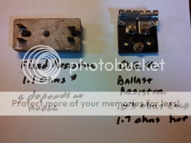
Here's the resistor assembly after it was removed. I would not mind replacing it as it looks dodgy... but I couldn't find anywhere that sells it. This one is brittle and falling apart.

mvphoto26986.jpg


Here's a nice photo of the battery back in the box and a shot of the cables. Someone suggested my cables might be kind of wimpy. Are these cables okay? Look okay to me.

mvphoto26987.jpg


Lastly, here is a shot of the new resistor block. I plan to use the junction post on the oem resistor block rather than the ammeter. Do you suppose the parasitic draw is because the alternator is always "on" the way it is wired now? I suppose I will find out when I do my re-wire.

(I will use LaRue's excellent wiring diagram to set things up.)

I do not plan to use the 6 volt coil any more - but a 12V with the new ballast resistor - this way I will not have to wire in a second resistor.
 
(quoted from post at 13:42:28 09/04/15) Thank you for all of this! I could not figure it all out just by reading the manual. One assumes when you pay a mechanic to "set things right" that it's more than "just make it run". I think that's what my mechanic did - without delving into the subtle detail.

Here are some photos of the "Before" I read your suggestions.

mvphoto26980.jpg


A peak into the battery compartment. I bought a new battery box to replace the rusted out original - but the new battery box has a metal plate to hold things down... and the battery conveniently locates contact so that the cable will short out the system unless one relies on the paint to serve as an insulator.

mvphoto26979.jpg


The ammeter is used as a junction - which I think is "bad form".

mvphoto26982.jpg


Inspecting my wires, I discovered this... and I looked for a site which had the length of the ignition wires so I do not have to buy a whole set to replace one. Guess I'll just pull the old one out and take it in.

When I came back from vacation my battery was dead, so I charged it up and began my search for the parasitic draw... which was about 6.5 mA if I did my meter setting correctly.

mvphoto26983.jpg


I tracked it down to the alternator - which is weathered.

mvphoto26984.jpg


I pulled off the resistor assembly and saw the rust bleeding over the assembly. Could that rust bleed cause the short?

mvphoto26985.jpg


Here's the resistor assembly after it was removed. I would not mind replacing it as it looks dodgy... but I couldn't find anywhere that sells it. This one is brittle and falling apart.

mvphoto26986.jpg


Here's a nice photo of the battery back in the box and a shot of the cables. Someone suggested my cables might be kind of wimpy. Are these cables okay? Look okay to me.

mvphoto26987.jpg


Lastly, here is a shot of the new resistor block. I plan to use the junction post on the oem resistor block rather than the ammeter. Do you suppose the parasitic draw is because the alternator is always "on" the way it is wired now? I suppose I will find out when I do my re-wire.

(I will use LaRue's excellent wiring diagram to set things up.)

I do not plan to use the 6 volt coil any more - but a 12V with the new ballast resistor - this way I will not have to wire in a second resistor.

You likely have a 3 wire alternator that has a real crappy way to make it behave as a one wire alt. That is the resistor across the #1 to #2 terminals at the alt plug. That is no doubt the source of your 6.5 ma drain. A real 3 wire alternator will have a drain of less than 1 ma and a decent one-wire alt about 1 to 2 ma drain. I would use a diode in the #1 lead to the ign key sw, trash that resistor across #1 to #2 and get on with life.
 
Ok, thanks JMOR!

I see that I can buy one ready made for $18 or build one with either a 3A diode or a 194 light bulb (idiot light) and a two spade plug. I'm sure I can round up those items for less than $18 - I'll opt for the light bulb as there is greater than 50% chance I'd put the diode in backwards. :)

Nice reference that explains all this: http://bob_skelly.home.comcast.net/~bob_skelly/alternator_conversion/wiring_alternator1.html
 
I have slowly got away from diodes and bulbs and went with a ignition switch that will turn off/on the alt. I found this handy dandy switch this week that fits a N nicely NAPA KS6041... Just wire the alt switch to the ACC side of the switch life will be good.. You also will knock out 2 birds with one stone and get shed of that lousy aftermarket style switch, its not a matter of if it will fail its when it will fail...

BTW a Volt meter is a nice up grade... Dump the amp meter its pert neer useless....

http://forums.yesterdaystractors.com/viewtopic.php?t=1239210
 

Thanks Hobo!

Providential that you sorted this all out in time for my maintenance work!

I'll replace them both. I especially like the voltmeter!
 

Thanks! I need that! Didn't know it existed. thought I was going to use plastic tie wraps... which is not a pretty solution.
 

Thank you Hobo, JMOR, SoundNguy and Bruce!!

After your exhaustive explanations and reading of older posts I think I figured out the 12V electrical. I was pleased to install the OEM resistor as Bruce suggested - do the meter work that SoundNguy encouraged (found the parasitic drain) - and installed the cool switch suggested by Hobo - and a voltmeter that I am not thrilled about... but it's better than the ammeter.

I installed a 12 coil, sand blasted my spark plugs, put a new spark plug wire in (used Bruce's soapy water technique to pull it through). It starts and runs better than ever. Thanks guys!


Video on my digital voltmeter - the meter is less than amazing.

https://youtu.be/ePtqXekZOkA

Regarding the volt meter - I know the alternator is charging because I can start out at 12.4 and park the tractor with 12.8. I usually do short runs - not hours of running.
 

Good idea Hobo! I thought about it last night thinking the acc side is suppose to have a resistor in it that is supportive of the alternator - so I moved it over to the "on" side of the switch this morning thinking it would have the full voltage support - but it behaves the same.

I had the thought that once the 3 second tolerances are tripped the thing goes into "warning" mode and will not return to normal function unless the meter is reset. So, I hooked a jumper to the red wire, started the tractor and then connected the jumper to the connector after it was running - it went directly to "warning" mode.

So, I conclude the digital reader is faulty. I read a comment on Youtube where the author complained about the same problem... (could mean both of us don't know how to set it up, but I tried lots of different hookups)

I expect it's the microcontroller part of the gauge has bad logic.

I'll leave it on for a while and see if the behavior changes when the battery is fully charged. Even the way it works - it's better than the ammeter.
 
It should function anytime the switch is in the on position...
Unless its just bad are your solid wire core plug wires and non resistor plugs may be the issue...

None of my digital test equipment works satisfactory around a N unless I move it far away from the engine while run'N...
 
I don't know if my plugs are non-resistor - but I think the wires are solid core as the one I replaced was... and the one I replaced it with was solid core.

How far away do you have to get with your test equipment for it to work? I can wire it up and move it a distance away. If that's the case could I "shield" to make it work? (Not sure what a good shield would be...)
 
(reply to post at 23:18:36 09/23/15)

I would install a analog meter on it and call it a day...

http://v2.us.sparex.com/ItemDetails/ItemDetails.aspx?ItemNumber=614289

On my own chit I run graphite core wires are what ever they call'em these days... RFI is generally not a issue unless I am right on top of the engine while its run'N...

My digital timing light goes haywire around a solid core plug wires and non resistor plugs...

My Digital DVOM has to be about 5/6ft away to give any type of sable reading. Its giving me issues at this time I have not tried any of the others on a N... All my meters are top of the line are priced that way... :lol:

I would not put up with it like you have it now...

You could wire it directly to the battery to test it are take it to your car/truck for a test.... I am leaning toward a RFI issue...

JMOR are Soundguy would be in the know on the technical part of that deal I am just a over paid grease monkey...
 

Ha! You inspired me! I have a second meter - so I ran some wires about 12 feet long to hook up the second volt meter and ran through my tests. It worked fine after I started it up. I could see the voltage gradually climbing... very cool... though I noticed each meter differed by .1 volt.

I then took the meter and sat it on the dash next to the other one that had the warning light glowing to see if it was an EMF issue and #2 meter performed okay while meter#1 was still blank.

So, I decided meter #1 was messed up and replaced it with the working meter #2. Took the old one out, soldered on new connections on meter #2, dropped screws in the gravel and looked for them... all that stuff I do when I put things back together. What do you think? Got it all back together and it performed just like meter #1!! Blank display.

I think it has something to do with the length of the wires maybe... but only Mr. Science would know the answer to this one.

I have a MF-35 that I plan to put the other one in... which should answer the question, "Why he'd buy two!"

Your Sparex is for dealers only - but Ebay sells 'em: http://www.ebay.com/itm/772995M91-N...-Meter-Gauge-2-Diameter-12-Volt-/231288538596
 
I think the tin was acting as a shield...

Yes that's the sparex meter 8) I am a dealer so I guess my cookies took me straight to it when I punched in the #.... With free shipping it looks like a good buy...
 

We sell tractor parts! We have the parts you need to repair your tractor - the right parts. Our low prices and years of research make us your best choice when you need parts. Shop Online Today.

Back
Top