Update on Hydraulics

RobBruno

Member
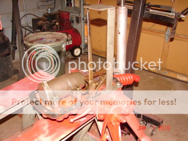
I have finally put all of my 8N hydraulics back together. The lift had stop working entirely. For the longest time, the only way the lift would go up is by having the quadrant lever all the way up and push down on the draft control lever. Then, about this time last year, it stopped working all together. With help from people from this board, here is what I did:
1. Replaced the relief valve
2. Dropped pump and removed the valves and cleaned entire sump and pump.
3. Straighten one of the valve guides that had gotten bent.
4. Replaced the three rings on the cylinder piston
5. Honed the cylinder before replacing the rings
6. Replaced the cam follower pin.

When I had everything a part and had replaced the pin, I noticed that so much of the linkage was worn out, I am not sure how much contact the pin is actually having with the pin.

Now the pump works in that it will lift the implement VERY slowly. But, I still need to press down on the position control lever to get the lift to work. Before, even though I was pushing down on the position control lever, the implement would go up quickly. I adjusted it the best I could with the directions in the manual and the quadrant is pushed all the way towards the rear of the tractor as it can get. It also leaks down much faster then before. I thought the exhaust valve might be stuck open but when you lower the quadrant it drops quicker then when it just leaks down. The piston and cylinder which I thought were in great shape with not a lot of scratches and certainly no gouges I thought would be fine with just replacing the rings. So, the lift is working, but not great. I can get through the winter and then get back into it in the spring. So now my questions are:
1.Does it take time for the rings to set or "break in" to seal the piston in the cylinder?
2 Could the lift be very slow cause the valve is barely open because of the adjustment? Also, could this adjust effect the leak down.
3. If the linkage is so worn that the cam pin is not following the cam, is there any way to really adjust the linkage to make it work?
4. What would cause the lift to go up slowly.


I realize I will be going back into this system when the weather breaks cause I would really like to have one that works at least a little better then this.
 
if you didn't adjust the linkage, then you didn't finish the job and no conclusions can be drawn.. YET.
 
I tried to adjust based on the dimensions in the repair manuals. Are they not correct or does the jig show something else? I am not familiar how the jig would work.
 
The manual sets the adjustments for new parts. Yours are worn. The jig provides a fixed reference point from which adjustments are made. Attach the jig to the lift cover (as in the pic) then make the adjustments.
ZanesJig.jpg

75 Tips
 
(quoted from post at 13:35:45 01/27/15) I tried to adjust based on the dimensions in the repair manuals. Are they not correct or does the jig show something else? I am not familiar how the jig would work.
e all have our own ways of approaching these problems & all will achieve the desired results although via different paths. Said that. Now, if it were me, with your symptoms, I would find out where your system is leaking before spending time on adjusting. Clearly, from what you describe, you have leaks. Maybe thru a less than closed valve (adjustment?), but still a leak. Remove the right side inspection port, use light/mirror/etc. and look for fluid coming from somewhere, above, front, rear, below surface of oil, at pump, where on pump, etc.
Places to look:
 
Soundguy. Yes, used all three. I will look for leaks as well. I know when we rebuild motors, it takes only a few minutes but it did take time for the piston rings to seat in a newly honed cylinder. Didn't know if it took a couple uses for the new rings to seat in the cylinder.
 
With an old bore and rings you get what you get. Look for leaks,
if no bad ones, ... adjustment.

Remember non opening control valve yielding slow Hyde is an
adjustment issue.. etc
 
testimonial: bought and used one of Zane's jigs. well worth the money. and good phone support as well. really can't go wrong. and it removes one variable from the system.
 
(quoted from post at 22:13:52 01/27/15)
(quoted from post at 13:35:45 01/27/15) I tried to adjust based on the dimensions in the repair manuals. Are they not correct or does the jig show something else? I am not familiar how the jig would work.
e all have our own ways of approaching these problems & all will achieve the desired results although via different paths. Said that. Now, if it were me, with your symptoms, I would find out where your system is leaking before spending time on adjusting. Clearly, from what you describe, you have leaks. Maybe thru a less than closed valve (adjustment?), but still a leak. Remove the right side inspection port, use light/mirror/etc. and look for fluid coming from somewhere, above, front, rear, below surface of oil, at pump, where on pump, etc.
Places to look:

Whut he said looks like you have multiple issues one taint gonna fix the other... Research your leak then apply a battle plan to take care of your issues in one dive...
 
I know this thread is a month old. I like seeing the Zane adjustment tool but ALL the posts from him is basicly a "YOU HAVE TO HAVE MY TOOL" to adjust your 8n come on. I have the top cover off Dad's 8n. After doing a lot of measuring from the top cover bolt holes to the pump bolt holes, to the valve control - using a square, micrometer, offset depth gauges, ETC to find the exact postion the ball should be. I found between the 2nd and 3rd bolt hole on the top cover a little circle marked in the gasket surface. It lines up EXACTLY with ball on the control arm to the pump. Wonder if Ford marked the postion for those whose don't have $65 bucks to blow on a once in a lifetime use tool. If the top cover has been filed, scraped or wire brushed the mark most likely not show. My background is in drafting and machine design.
 
(quoted from post at 12:25:36 02/09/15) I know this thread is a month old. I like seeing the Zane adjustment tool but ALL the posts from him is basicly a "YOU HAVE TO HAVE MY TOOL" to adjust your 8n come on. I have the top cover off Dad's 8n. After doing a lot of measuring from the top cover bolt holes to the pump bolt holes, to the valve control - using a square, micrometer, offset depth gauges, ETC to find the exact postion the ball should be. I found between the 2nd and 3rd bolt hole on the top cover a little circle marked in the gasket surface. It lines up EXACTLY with ball on the control arm to the pump. Wonder if Ford marked the postion for those whose don't have $65 bucks to blow on a once in a lifetime use tool. If the top cover has been filed, scraped or wire brushed the mark most likely not show. My background is in drafting and machine design.
nder what conditions?
" I found between the 2nd and 3rd bolt hole on the top cover a little circle marked in the gasket surface. It lines up EXACTLY with ball on the control arm to the pump. " For LIFT, LOWER, NEUTRAL? Where is Touch Control under these conditions? Where exactly is the mark? Is it one inch away from the 2nd hole edge toward the 3rd hole for example?
 
.950 inch from the rear edge of 3rd (center) hole
toward the rear of the top cover under the quardant
portion. Position of all levers and arms are for the
Draft control adjustment procedure. Not going to
enter into a debate about this little mark - just
surprized me to find a marking that coincidices.
 
(quoted from post at 20:24:48 02/09/15) .950 inch from the rear edge of 3rd (center) hole
toward the rear of the top cover under the quardant
portion. Position of all levers and arms are for the
Draft control adjustment procedure. Not going to
enter into a debate about this little mark - just
surprized me to find a marking that coincidices.
o interest in debate here either. Very interesting. Thanks for posting! Looks like that is essentially centered between the two holes & should be NEUTRAL position for the control valve.
Thanks again.
 
Not centered since the measurements are from the
rear edge of center hole - .950 to front edge of
mark - a .300 diameter mark - then 1.520 from rear
edge of mark to front edge of next bolt hole on
back side of quardant. Also found it intersting
the .300 diameter mark is the same diameter as the
ball on the pump control arm.

Not Netural postion. Position- Draft control down
in DRAFT position. Touch Control lever on quadrant
full up. Pump Control arm up against Draft Spring.

Course this is an early 48-49 8n with the tension
style nut - not the castellated style adjustment
nut, so all the spring adjustments didn't follow
the new FO-4 book. Had to do a lot of searching
and found the old adjustment precedure for the
spring adjustments for the tension style nut. Wish
Penton I&T had included both style of adjustments
in the FO-4 book.

After all the painstaking measurements and setting
the ball end of the pump control level, I saw the
small circle. It is very light and does not even
take marking paint or I would have tried to post a
pic of it. Checked the mark VS the ball and it is
pretty dead on.
 
(quoted from post at 21:47:21 02/09/15) Not centered since the measurements are from the
rear edge of center hole - .950 to front edge of
mark - a .300 diameter mark - then 1.520 from rear
edge of mark to front edge of next bolt hole on
back side of quardant. Also found it intersting
the .300 diameter mark is the same diameter as the
ball on the pump control arm.

Not Netural postion. Position- Draft control down
in DRAFT position. Touch Control lever on quadrant
full up. Pump Control arm up against Draft Spring.

Course this is an early 48-49 8n with the tension
style nut - not the castellated style adjustment
nut, so all the spring adjustments didn't follow
the new FO-4 book. Had to do a lot of searching
and found the old adjustment precedure for the
spring adjustments for the tension style nut. Wish
Penton I&T had included both style of adjustments
in the FO-4 book.

After all the painstaking measurements and setting
the ball end of the pump control level, I saw the
small circle. It is very light and does not even
take marking paint or I would have tried to post a
pic of it. Checked the mark VS the ball and it is
pretty dead on.
here is the control valve when all is as you describe?
Full LIFT shown in first picture & full LOWER in second. NEUTRAL would be about mid point of those extremes.

 
JMOR I'm not as stupid as you think I have told you
it was FULL UP ON INTAKE for the DRAFT CONTROL
SPRING ADHUSTMENT PROCEDURE. TOLD you positions of
each and EVERY LEVER. If you have to have your hand
held and lead thrugh each of my replies maybe it is
you that needs to go to the book and follow along.
 
(quoted from post at 11:23:35 02/10/15) JMOR I'm not as stupid as you think I have told you
it was FULL UP ON INTAKE for the DRAFT CONTROL
SPRING ADHUSTMENT PROCEDURE. TOLD you positions of
each and EVERY LEVER. If you have to have your hand
held and lead thrugh each of my replies maybe it is
you that needs to go to the book and follow along.
ohhhh! Far from thinking that you are stupid. Just the opposite & very clever & no doubt time consuming in trying to determine something that I have pondered for years. Maybe I do need hand holding. Just like you, I have wanted to know where the control rod ball was being set to when making the various adjustments. I tried to make a correlation between 3 different setup procedures, Zane's, GO4Rain procedure (widely circulated on WWW) and Ford's using the NuDay setup tool HG-101, and I failed.....never could achieve correlation. I sincerely apologize for making the wrong impression & do appreciate all input, such as yours. Results I came up with, all no match:
 
Ok Sorry here too. Didn't understand you were trying to figure out where my little circle related to with all the other adjustment procedures you have found.

Haven't seen Go$Rain's procedure. I found a link but AOL just puts me back to my own profile. ????? If you got a better link or even the procedure it's self I'd like to see it. Onless his is the canpanter's square clamped to the top cover = Seen it.

Are the markings centerline of the pump control arm ball?

I think my email will show - just email me. I am taking pics and a full procedure on how I got all the measurements and end result.
 
" I tried to make a correlation between 3 different setup procedures, Zane's, GO4Rain procedure (widely circulated on WWW) and Ford's using the NuDay setup tool HG-101, and I failed.....never could achieve correlation."

JMOR, thanks for the picture with dimensions for control rod position from several repair sources.

This has been tabu information for too long.


Ed P., Thanks for your numbers also. I didn't see the little circle (you found) when I had mine dissembled. Surely will look in the next lift job!
 

We sell tractor parts! We have the parts you need to repair your tractor - the right parts. Our low prices and years of research make us your best choice when you need parts. Shop Online Today.

Back
Top