Kevin in MN
Member
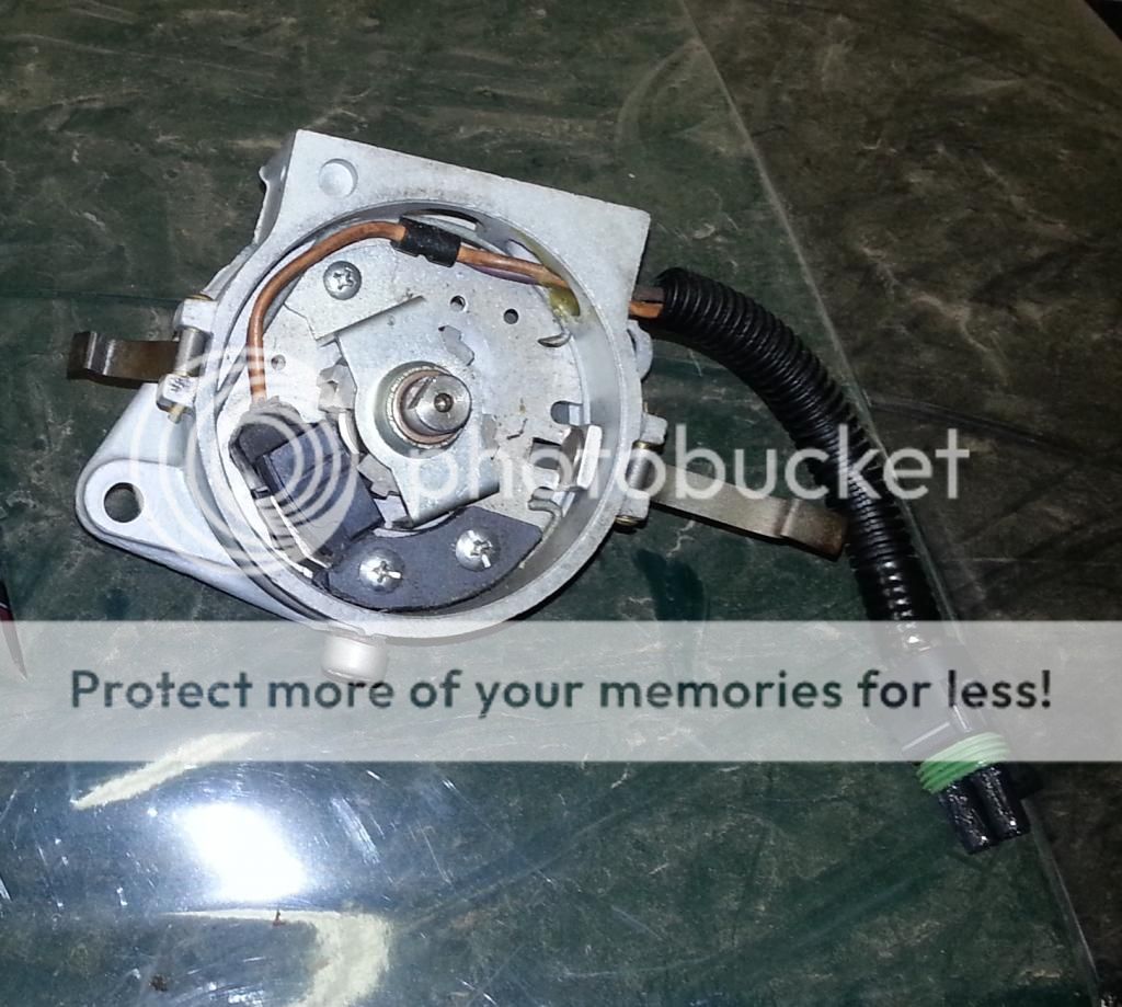
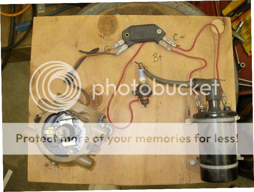
I built an electronic ignition to use a ford reluctor and pickup and an HEI module. Worked great on the bench. My first install attempt I warmed up the tractor made sure it was running good then shut down and swapped the points distributor for the EI one. It started right up but timing was off more than I could adjust out. That was a week ago. In the mean time I pulled the distributor and rotated the reluctor on the shaft to get the timing closer. Yesterday I reinstalled on cold tractor and now I have no spark from the coil. I pulled the distributor and if I spin the shaft I get good spark. Reinstalled again no spark. All I can think of is the distributer rpm’s in a cold engine are too slow to get a good pulse to the module? Any ideas?


")