(quoted from post at 10:45:51 01/28/13) Good work TOH.
Found three N series front end loaders on ebay.
One is a "Dearborn Farm Equipment" label loader, mounted on the tractor.
Another appears to be a home brew design mounted on the tractor
The third is a basket case & removed from the tractor.
The two tractor mounted loaders appear to be attached to the front axle support weldment allowing rotational movement of the front axle about the king pin.
This design places the king pin and center axle hole in the load path to ground, placing load on the weakest spot on the center axle.
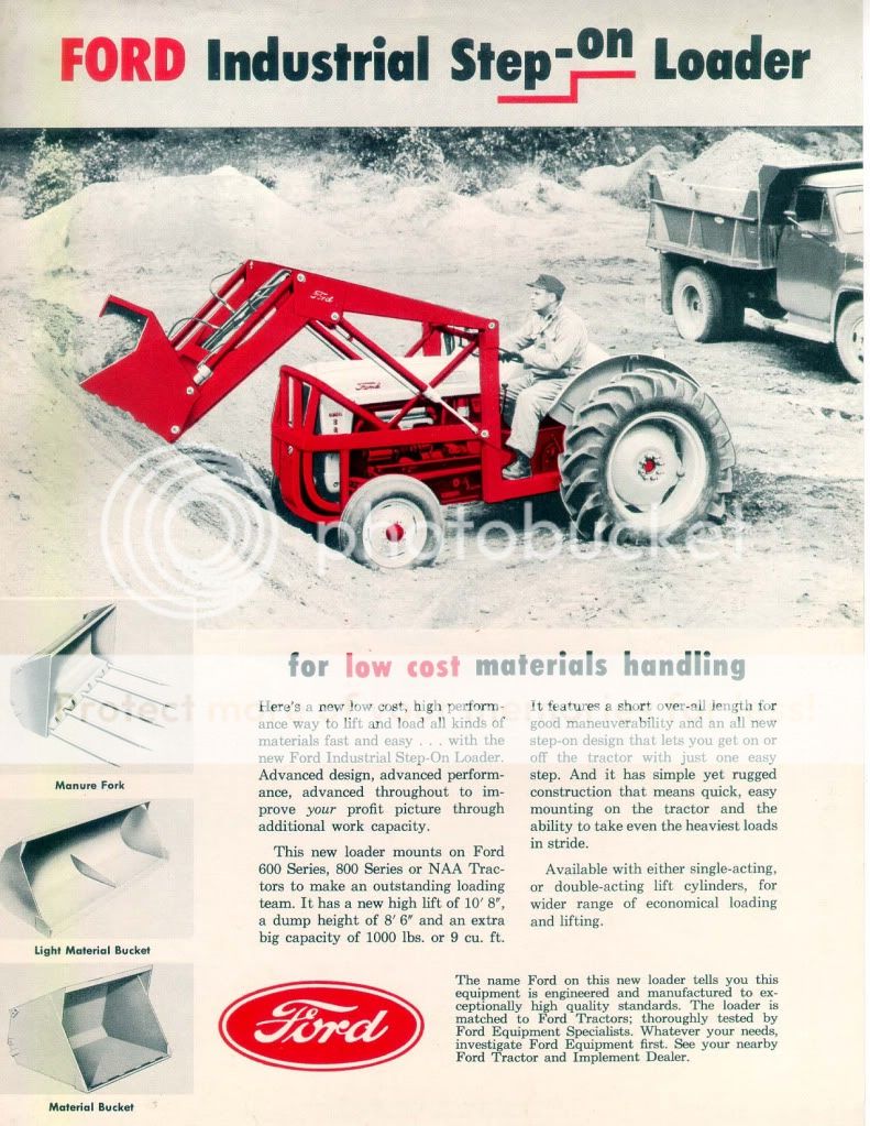
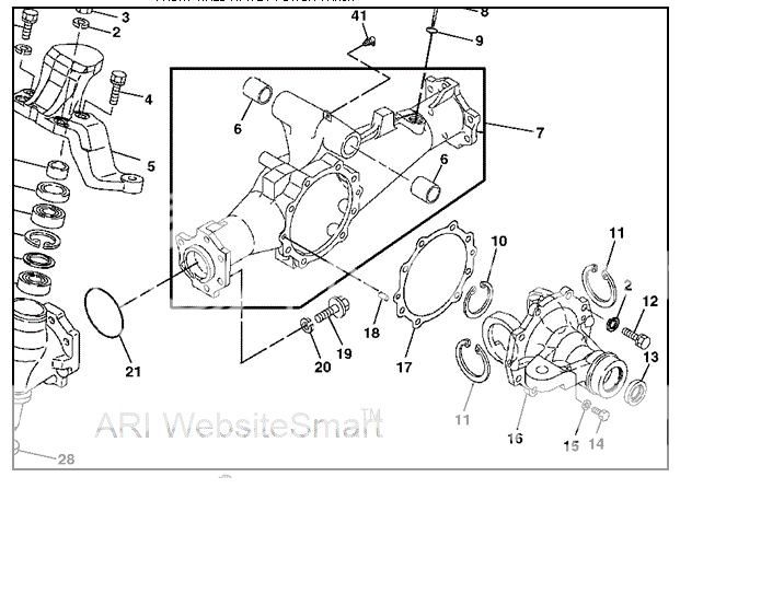
However, the Ford industrial loader you posted appears to be attached to the front knee, which is cast steel. Noticed there are two holes on the knee extension adjacent to the vertical cylinder that houses the forged spindle.
These holes are not used to attach the center axle to the knee extension.
Believe this to be the attachement point for the Ford "industrial" loader. This attachment point takes the center axle out of the load path to ground. This attachment point would be much prefered over using the center weldment support,
as was used on the Dear farm equipment design.
However, using the knee extension holes to attach the loader frame would fix the center axle and prevent it from rotation.
Found a 1959 sales brochure for a Ford 703 loader design for a NAA, 8N , Oliver, 55 MF tractor with a 1300# load capacity.
The brochure is titled" Ford extra heavy duty loader series 703".
This loader also appears to be attached to the knee extension rather than the center support.
After many years of farm work fatigue cracks could develop in the axle sand casting or knee extension sand castings, even if there were no initial flaws in the castings. My 8N spent 60 years plowing corn fields in Merced, CA.
Before straping on a loader to N series, would have the center axle and knee extension parts checked for cracks, especially for the center support mounted type for safety.
After checking the center axle and knee extension for cracks could increase the allowable working load on the center support from 400# to 800# and believe N series would safely handle a 1000# payload on the Dearborn Farm Equipment type loader, since a portion of the pay load and loader frame weight is shared by the rear axle.
For comparison found some loader ratings on current tractors of similiar HP to the N series.
NH T1500, 30 HP: 875# load capacity
JD 1 series,22-25 HP: 825# load capacity
JD 2000 series, 24-30 HP: 1023# capacity
JD 3000 series 23-30 HP: 1186# capacity
These tractors all have support frames for the engine rather than a "stressed engine design" like the N series..
All have fixed front axles that do not rotate compared the N series.
The loaders are attached to the fabricated tractor frame with no sand cast parts.