Delco 10-si alternator Diode

TB in MN

Member
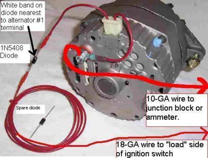
A couple weeks ago I replaced my alternator with a 3 wire Delco 10-SI on my 2N front mount distributer. I soldered radio shack diode 276-1661 on the 18 gauge wire before the alternator as shown in the photo. The white band is on the alternator side as shown but the diode was allowing battery voltage back through the alternator. Today I replaced the diode which I checked was working properly before I hooked up the battery. After the battery was connected I measured 12V again at the alternator. I then checked the diode and found it to be leaking voltage again. What could be the problem?

Thank you,
TB in MN
a53080.jpg
 
TB........would it surprize you to learn that you will read 12V on BOTH sides of the isolation diode while yer engine is running???

ONLY when you turn yer ignition switch OFF, will you read 12V on the alternator (banded) side and ZERO volts with the ignition switch OFF. Understand the difference??? .......Dell, retired electronic engineer
 
Dell,
I am reading 12 Volts on the alternator side with the ignition switch off. This has been and will continue to drain my battery. Isn't the purpose of the diode to prevent this situation?

Thank you,
TB in MN
 
Likely, a diode(s) has failed in the alternator's internal rectifier bridge.
 
TB,

Like Dell said,

12V on the alt side of your diode with ign off is normal.

If ign switch is off, then where ohh where can any current go?
Surely not through the reverse biased diode and never through an open switch.
The internal alternator leakage current is also normal, less than 1 milliamp.

Alternator has two sets of 3 phase, full-wave bridge diodes (six diodes per each bridge set).
You are able to read 12V (on alt term #1) through part of the bridge that is for the field winding regulator circuit inside.

Your diode will help supplement (with ign on) your field winding current to get charging going.
Once alt develops higher voltage than the battery, the alt takes over for the field winding current.

Other reason (main reason) for reverse blocking diode is so with ign off, no 12V will bleed through your points (if closed) to ground that originates from the field winding bridge diode pack.

Regards,

Greg,

The other electrical engineer.
 
I believe I understand my problem now. Switch side of diode was connected battery rather than the ignition switch. It was one of Dell's unlimited ways to incorrectly wire an alternator . Live and learn. Thanks for the help.

TB in MN
 
that wire has to be connected to the coil side of the ignition switch.. not battery side.

soundguy
 
TB,
I hope you have your diode finally to the load side of the ign switch like you mentioned.

I hate to keep jerking you around.

I investigated my own 10-SI while following the schematic in the data sheet for it.

Guess what, NO 12V on term #1 with ign off!!!

I jumped the gun in defense of Dell who may be right with other alternator models?

I was wrong at least with the 10-SI assuming that the 12V could get through the Diode-Trio to term #1.
With ign off, the battery voltage is blocked by the main full-wave bridge positive side diodes.

And yes the field winding regulator diode-trio is also full-wave, its other three diodes are shared from the main bridge diodes that go to ground.

OK now;

The REAL reason for your diode in lieu of using an idiot lamp with lots of resistance is this;

The internal diode-trio is only intended to power the internal field winding current regulator.

Your diode blocks any charge current originating from the diode-trio (when running) from going out of term #1 through the ignition switch and to the battery, and also ignition current to a degree.

Regards,

Greg,

The engineer still in training :)
 

We sell tractor parts! We have the parts you need to repair your tractor - the right parts. Our low prices and years of research make us your best choice when you need parts. Shop Online Today.

Back
Top