12V System not charging

jlsanborn

New User
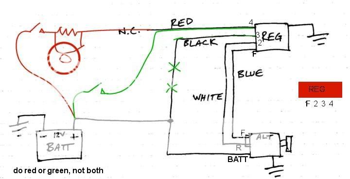
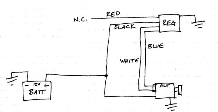
So, I've read a number of the topics here on the 12V systems, but have not really found what I need, which is basic troubleshooting of the alternator / regulator circuit. My old beast has the "typical" re-wire job, which needs to be cleaned up. I shoulda snapped a few photos so you all could get a good laugh! Regardless, the thing worked when I got it so that was a ways down on the priority list, until yesterday that is, when it quit charging. Last night I un-tangled a bunch of what's there and sketched out what I found. Seems to me that the hot wire to the regulator should be switched. It also seemed odd to me that above mentioned "hot wire" was the black one and that the red wire was not connected. With the tractor running there is no voltage at either of the smaller (blue and white) wires at the alternator. The large wire reads battery voltage. The black wire at the regulator measures battery voltage. Whatchya think???
John
r5290.jpg
[/img]
 
I'm not certain what alternator it really is, other than it's got one large post for the BATT connection, then another two pole connector. I expected to see field supply voltage at one of the smaller ones (from the regulator?).
 
My regulator does not appear to be the original??? Just guessing by the way it's mounted. I do believe however that some alternators use an external regulator.
 
There were many alternators that used external voltage regulators.
Delco 10Dn as below was one........your look like this? Or is connector different/different location?
alt_Delcotron_10DN.jpg
 
That'd be the one!
I've been doing a little online research and found an external regulator setup like I've got. The wire colors are a little different, but there are two (rotor and field) from the regulator to that alternator. On is connected to the battery (bonded - not switched) and the fourth just shows headed off to the system (alt light???). So, I'd say that it's probably hooked up as it should be, but something has gone wrong. Shouldn't the regulator be dishing up 12V to the field?
r5291.jpg
 
The sketch you found is marked FORD and the alt picture I sent is a GM (now Government Motors) Delco 10-DN.

Look closely for terminal numbers 1,2,3,4 on your regulator.
Attached is the GM diagram & if modified by red & green mark up, you can get by with a simpler connection.
10DN_connex_2.jpg


See Ford/Delco difference?
alts_GM_Frd.jpg


A Ford ext reg ckt:
fordalt2.jpg


Or Ford SIMPLE:
FordAlternatorCircuit.jpg
 
Thank you very much for the sketch! I may have jumped too quickly in saying "that's the one". From memory, it looks very very close. I'll have another look here this evening and see if it's exactly the same or if there are any identifiable numbers. I'll snap a photo too.
The sketch is a little misleading in that there are two alternators there. One is diagramatic and the other is pictoral, yet they are both connected? It is very helpful however and I'll chase down those connections. In a nut-shell, it looks like I should have voltage at the field terminal though.
John
 
Generally, the voltage to the field is only a fraction of the 12v battery voltage until engine running & alternator putting out & even then it is regulated and will most often be higher than with engine off but less than 12v.
 
Yep, that'd be the one! Took a few photos just cuz I said I would. I'm going to confirm continuity between the connectors at the regulator and the alternator, but I'm guessin the regulator is toast.
Thanks again for you help!
r5292.jpg
r5293.jpg
 
I wouldn't get a new reg just yet. Now that I know what you have, I don't believe that the system would have ever charged when connected as per your early sketch of wiring.
I have marked your sketch up in both red and green. Please note the physical layout of reg terminals at right.

I suggest the green mark up since you need no new/additional parts & it is simple. Cut black wire to reg #3 and add green wire from Ign switch.

Alternately, you could leave all wiring in place as you have it, but ADD the resistor (~10 ohms) and idiot light in parallel with it (or some people use just the light bulb or just the resistor) as shown from the ign switch to reg terminal #4 as in RED. I believe if you skip the res/light & connect ign sw directly to #4 then the tractor may not turn off when the ign is switched off, assuming alt/reg is charging OK.


alt_10DN_reg_connex.jpg
 
Per the green diagram, the only change to what I have now would be to add the switch in the black wire. I thought it was odd that the regulator would be "hot" all the time? With that said, why would you feel that it wouldn't work as is?
Thanks again!
 
(quoted from post at 13:40:50 07/17/09) Per the green diagram, the only change to what I have now would be to add the switch in the black wire. I thought it was odd that the regulator would be "hot" all the time? With that said, why would you feel that it wouldn't work as is?
Thanks again!
If you go back and look at my diagram/picture if alternator combined with schematic representation of diagram, I'll try to explain that regulator as to why not work with #4 not connected. If no power to #4, then there is no power either thru the normally closed Voltage Regulator contacts (upper right) or thru the lower left resistor for the alternator Field. Since the alt Field has no power, the alt cannot generate any output, so the "R" terminal which is connected to & controls the Field Relay (#2) can never be energized. It must be energized in order that its contacts close and connect battery power (#3) to #4 for supplying the Field power.
It may sound like a circular argument to you, but think of it this way: the field receives 'tickle or wake up" power via the resistor & light bulb, that make it put out something, which is enough to pull in the Field Relay which now provided battery power to the Field so that it can really output significant power. That explains why it wouldn't work as per your diagram.
The next question you are going to ask (unlike Dell, I do have a crystal ball), is "why will it work if I add the green connection from my ignition switch to#4 & leave #3 disconnected? This simply removes the Field Relay from the picture, short cuts its function and supplies Field power to the alternator (via reg terminals #4 & F) without the use of the Field Relay as soon as ignition sw is turned on whether alt is outputting or not.
NOW, and this is IMPORTANT...........in explaining, I realized that I erred in my drawing of the green wire from ign sw to #3........it should be ign sw to #4, with #3 being a no connect. Corrected below.
alt_10DN_reg_connex_corrected.jpg

The same as in my original mixed schematic/blue alt picture diagram.
With any luck, this doesn't leave you more confused than ever.
 
Not at all and I really appreciate you taking the time to walk me through it. I didn't have time, but to snap those photos last night. I'll dig deeper this weekend. What has me perplexed is that I'm certain it was charging. I've run the battery down more than once trying to crank on a crappy running / hard to start engine. I ended up jump starting with the pick-up and the tractor always re-charged the battery. Everything was good until I changed the points and coil last week. Boy the tractor started and ran better, but also ran the battery down.
 
Well, thanks to your help I'm charging again! Using my ohmeter and the diagram of the regulator I rang out the terminals, figuring it was bad. I then pryed off the cover and found......

r5295.jpg


Jiffy little solid state thing!

Napa had the "old school" electro-mechanical GM VR, but it set me back $60!!! I hooked it up like your "green" method and bingo.....15V at the battery! Then promptly added the ballast resistor back into the ignition circuit like I had been meaning too so I don't roast my new coil.
Thanks again for all the help!

John
 
(quoted from post at 14:01:52 07/20/09) Well, thanks to your help I'm charging again! Using my ohmeter and the diagram of the regulator I rang out the terminals, figuring it was bad. I then pryed off the cover and found......

r5295.jpg


Jiffy little solid state thing!

Napa had the "old school" electro-mechanical GM VR, but it set me back $60!!! I hooked it up like your "green" method and bingo.....15V at the battery! Then promptly added the ballast resistor back into the ignition circuit like I had been meaning too so I don't roast my new coil.
Thanks again for all the help!

John
he one you pictured (both on tractor & now) should have been the SS functional equivalent to "old school" electro-mechanical & should work interchangeably.
Glad you are up & running.
 

We sell tractor parts! We have the parts you need to repair your tractor - the right parts. Our low prices and years of research make us your best choice when you need parts. Shop Online Today.

Back
Top