8N position control spring

fran213

Member
w do you properly adjust the position control spring on an 8N hydraulic lift.I am following service manual instructions.It says to line up marks on the lift arms.I have several marks on my lift arms for some reason.Is there another measurment I can use to get the lift arms in the right position so I can make the adjustment?
 
(quoted from post at 14:18:30 03/05/18) w do you properly adjust the position control spring on an 8N hydraulic lift.I am following service manual instructions.It says to line up marks on the lift arms.I have several marks on my lift arms for some reason.Is there another measurment I can use to get the lift arms in the right position so I can make the adjustment?
o-4 says that when marks line up, the lift arms are in most raised position. Caution, the arms can normally be raised by hand to a point beyond which the lift ram can raise them.
 
Ha. So I am not the only one to have that problem.
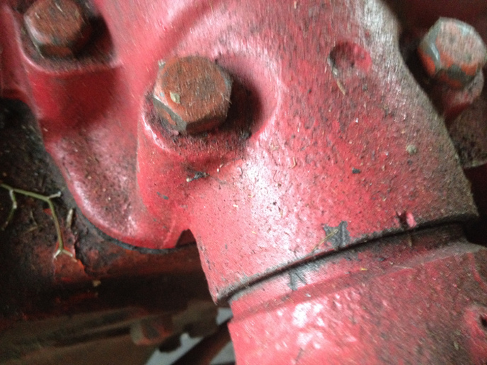
I took a best guess as to which marks. It was wrong. Had to take the top cover off again. Before I did, I made my own marks, V shaped so as not to get them confused with the several already existing marks. Then it worked out fine. BTW none of the existing marks were in the right place:)

later
deano
 
Which marks,my lift seems to have several.I am asking if there is another way to make this adjustment or another way to
figure out where the lift arms should be when making this adjustment because I am just not sure which marks are the correct
marks.Seems to me that someone put alot of these marks on here.I just don't want to have to pull the lift back out again.I
want to do this once.

Thanks !
 
When the two V shaped marks align the lift arms are at the top of their travel. The big mark top center of the housing is what I am guessing is the factory mark. There are no other marks on the housing. There is a faint line on the lift arm currently aligned with that big mark on the housing. That shows how far off that mark is from top of travel by the difference in my homemade marks. There are a couple more marks on that arm that are in random positions, you cannot see them in this picture.

I made these marks using the letter "V" from a number letter set, but you could just as easily use a cold chisel or center punch, whatever you have available to make your own distinct marks.

Of course you know that if there is wear on the shaft, bushings, cam, follower pin, bent control arm, or any other parts in there that or bent or out of spec that the "by the book" adjustment may not work for you.

I replaced the bushings, welded up the badly worn shaft and ground it back to spec on the lathe, replaced the cam follower in, welded up the grove in the cam and ground it back to its original profile, and straightened the bent control arm and the bent draft control rod. The "by the book" adjustment worked for me. Second time around that is:)

later
deano
a260120.jpg
 
What I am trying to ask is if there is another measurement i can use to find the spot that the lift arms are supposed to be in when I make the adjustment.I would really hate to put the lift back on and make the marks,then have to pull it back off and make the adjustment.

Thanks
 
If there is I don't know about it. There once was a web site/page that had a procedure for adjusting the position and draft control springs. The site no longer exists, but it was archived by the wayback machine. It gives the procedure from the operators manual, then how to check and straighten the control arm, then the quadrant adjustment from the operators manual. The images are missing, but still <a href="https://web.archive.org/web/20040822030423/http://members.aol.com:80/Go4Rain/hydadj.html">you may find this of some use</a> as it does give the lengths of the springs. If all of the parts in in good shape you may be able to get by by adjusting the springs to the lengths it says as those lengths should be the original factory settings. Note that there is a typo where it gives the length of the draft control spring. It says "The constant draft spring should be 3.58 inches long (slightly over 3/I6 inches is satisfactory) as shown in fig. 68." It should read "The constant draft spring should be 3.58 inches long (slightly over 3-9/I6 inches is satisfactory) as shown in fig. 68.".

Speculating here, but assuming that all of your parts are perfect, no slop and nothing bent, if you were to set the springs to the stated lengths and the control arm in the right position using Zane's jig or the carpenter square method, you could then position the upper lift arms so that the pin just touches the cam and the position control spring adjustment bolt contacts the control arm and that should be the "full up" position.

If you do that, then it would be a good idea to make a reference mark with a sharpy or something so when it is all back together and raised all the way up you can check to see if it in fact came out right:) And if it does, stamp the heck out of it!

In my case after straightening the control arm and the draft control rod (both of which were bent) and replacing the bushings and repairing the wear on the shaft, new follower pin and repairing the cam the lengths of the position control spring came out right at the stated value as close as I could measure. And it all works like it should:) Maybe you will get lucky:)

What puzzles me is how come there are no marks on my cover at the position indicated in the I+T f04 manual (unless I am blinder than I think I am and stupider too), and three marks on the right arm, and two on the left, and the marks are not in positions that would be consistent with swapping right for left or replacing a lift arm with one from another tractor, or with an aftermarket one. I thought in my case, that based on some other things I have found on this particular tractor, that it had at some point in the past been "makaniked on by monkeys". Maybe same monkeys got hold of yours too:)

later
deano
 

We sell tractor parts! We have the parts you need to repair your tractor - the right parts. Our low prices and years of research make us your best choice when you need parts. Shop Online Today.

Back
Top