
Just finished replacing the lift cylinder under the lift cover of my 135. When I disassembled it, I took care to put the control linkage back like it came apart because I don't have any of the special tools required to adjust the controls on the cover. Put it back together and it operates up and down, but it will blow the relief valve on the pump with the arms in full up position, but the position control lever is only about 3/4 up on the quadrant. I fixed this by adjusting the quadrant stop (one with two 7/16 nuts) down the quadrant to stop the lever before it comes up high enough to blow the relief. I don't think this is right to have to do, but it wasn't doing this before, and I feel I have the controls back like original. Any ideas.
You are using an out of date browser. It may not display this or other websites correctly.
You should upgrade or use an alternative browser.
You should upgrade or use an alternative browser.
- Thread starter BT73000
- Start date
Dieseltech
Well-known Member
- Location
- Akron, Indiana
Since the lift cover is not dowel pinned to the diff case it will shift a bit, could be what happened here. My guess is the position linkage lever still needs adjusted, but it will work as you have the limit stop set now..
ptfarmer
Well-known Member
- Location
- San Antonio, Tx
(quoted from post at 05:08:39 04/13/17) Since the lift cover is not dowel pinned to the diff case it will shift a bit, could be what happened here. My guess is the position linkage lever still needs adjusted, but it will work as you have the limit stop set now..
X2 ^^^^^^^^^^^^^^^^^^^^^^^^^^^^^^^^^^^^^
Here is what can happen when the position linkage lever is not adjusted correctly. Since yours didn't do this you are ok.

DavidP, South Wales
Well-known Member
Hello,
When you mention that the relief valve blows with the linkage fully raised is this to the lever position against the adjustable stop or is the linkage locked up so that you cannot lift it by hand any more. If the linkage is locked up tight this is a situation that must NOT be allowed to happen or the situation in the photo may occur. Are you absolutely certain that you replaced the levers on the correct side of the rollers in the internal linkage. If you have any doubts it would be worth draining the oil to the level of the bottom bolt and removing the side cover. Check the operation of the pump control lever relative to movement of the quadrant lever and 3-pt linkage. There are several posts of mine on here which will detail the way that the pump lever should move. With the linkage fully raised at the quadrant lever you should still be able to lift the end of the lift arms by one to one and a half inches.
DavidP, South Wales
Do you mind sending me the link to your other posts. My MF40 which uses a lot of the same components as the 135 and 165 is a without dashpot or pressure control version. I do have most of the Nuday tooling MFN 1080-D, and the MFN 970. However I could not find the Nuday kit 2267. I have had to take measurements off photos and hope they are close enough. I have not been able to find the dimensions for the original quadrant stop assembly. The 7/16" distance for the mounting bolt is all they give for set up. Without the bolt to stud distance apart and overall stop plate length you cannot set up position lever for rigging.
A note on cam alignment, After reading the service manual carefully. There is a difference as to where you place the levers to check this depending on if it is a pressure or non-pressure control. With both levers in transport (Non-pressure version), The cams are together but clocked as shown in the 40 manual but different than the 40B manual. I found this to be a little strange as they use the same shafts, and cam linkages. Any thoughts on this?
A note on cam alignment, After reading the service manual carefully. There is a difference as to where you place the levers to check this depending on if it is a pressure or non-pressure control. With both levers in transport (Non-pressure version), The cams are together but clocked as shown in the 40 manual but different than the 40B manual. I found this to be a little strange as they use the same shafts, and cam linkages. Any thoughts on this?
ptfarmer
Well-known Member
- Location
- San Antonio, Tx
I was looking on ebay yesterday, found this, and bought it, it should be here sometime next week. I'll get to see what kind of info it provides on special MF service tools.

You should have 3/32" of rotation difference, measured by index lines marked between the arms and the hitch cover. When you move the position lever past the transport stop and the relief blows that is your maximum up. The stop should be placed to prevent this and when you place the position lever in transport the arms should stop 3/32" before that. See Quick checks under troubleshooting in your service manual.
Could you send me an email after you get it. I would be interested in see what it says. What I have seen so far does not give details. Most of this tooling has not been made in a long time. We should put together a drawing file for discontinued tooling. Parts can be hard to find, and expensive. The potential for damage is great without the tools. The 1088-D and kit 2267 are used to set the adjustment block which changes the fulcrum point of the vertical lever in relation to the cams. After all of this I don't want to guess.
ptfarmer
Well-known Member
- Location
- San Antonio, Tx
Its the first book I've ever seen that's for special MF service tools. Hopefully it will have some info we can use.
(quoted from post at 11:36:07 04/14/17) Its the first book I've ever seen that's for special MF service tools. Hopefully it will have some info we can use.
I just went on Ebay and looked at that manual and another one from Nuday. I'm afraid that all it's going to be is a listing of all the service tools that once were available but now are not. The Nuday one was listed as kind of a collectible.
DavidP, South Wales
Well-known Member
Hi,
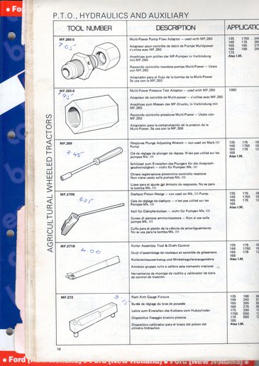
One of the attached photos shows the Churchill MF Special Tool 'Bible' circa 1975. The written in prices are in pounds
sterling. The 4 lower tools shown on the page are those required for the agricultural tractors but I'm not sure what
differences the industrial range has although if fitted with 3-pt linkage it would have made sense to fit the response
dashpot as it could be used for industrial implements. Could it have been removed?
DavidP, South Wales
Nuday and OTC produced tooling in the U.S., Churchill in the U.K. and elsewhere. I am curious if the MFN numbers were the same. On the issue of dashpots the answer is no. This change occurred in 1974, the easiest way to tell is the shape of the support bracket. No dashpots is triangular, Dashpot equipped bracket is rectangular. This MF40 also came with a early MKIII pump with a front casting 1 drawing number earlier than the parts book. later ones had the provisions to use a cartridge type relief if you wanted. This one is pressure control valve only unless you can find the conversion block to install a cartridge style valve. ($100 US for the only one I could find) The valve is adjustable and acts as the system relief when used in this application. The secondary relief is there, but has no function unless it has pressure control. A slightly updated version of this system with an auxiliary pump and mounted servo seems to be standard feature on the 40B. It was a work in progress I guess. Hard to make sure you have all of the right parts and information. thx for your input.
The dashpots were removed when they added the slide valve on the side of the rear casting of the pump to control response rate. It still works basically the same way. (relieving pressure in the intake gallery to allow the control valve in the pump to move to the discharge position). Although it would appear that the set up for position control is more critical and less forgiving. Very hard to get right without the tools as it's all about preloads on the vertical lever with the levers in a preset position and the MFN 970 presetting the cam position on the ram arm.
Yes I am fairly certain at I got the rollers on the ends of the quadrants positioned correctly on the fingers under the cover. The relief valve blows when the position control lever is about and inch away from aligning with the transport position stamping on the quadrant control. The lift arms also don't seem to go down as low as they should also. The draft control seems to work correctly throughout its range on the quadrant. The arms go further down than they do with the position control. Guessing almost 4 inches from the ground, maybe more. Position control only allows the arms to lower about 12 to 16 inches from the ground. I called the local dealer and they quote $370 for labor to r & r the cover and make adjustments. Probably just going to take it to them after the summer.
Similar threads
- Replies
- 0
- Views
- 66
- Replies
- 0
- Views
- 152
- Replies
- 2
- Views
- 361
- Replies
- 4
- Views
- 166
We sell tractor parts! We have the parts you need to repair your tractor - the right parts. Our low prices and years of research make us your best choice when you need parts. Shop Online Today.
Copyright © 1997-2024 Yesterday's Tractor Co.
All Rights Reserved. Reproduction of any part of this website, including design and content, without written permission is strictly prohibited. Trade Marks and Trade Names contained and used in this Website are those of others, and are used in this Website in a descriptive sense to refer to the products of others. Use of this Web site constitutes acceptance of our User Agreement and Privacy Policy TRADEMARK DISCLAIMER: Tradenames and Trademarks referred to within Yesterday's Tractor Co. products and within the Yesterday's Tractor Co. websites are the property of their respective trademark holders. None of these trademark holders are affiliated with Yesterday's Tractor Co., our products, or our website nor are we sponsored by them. John Deere and its logos are the registered trademarks of the John Deere Corporation. Agco, Agco Allis, White, Massey Ferguson and their logos are the registered trademarks of AGCO Corporation. Case, Case-IH, Farmall, International Harvester, New Holland and their logos are registered trademarks of CNH Global N.V.
Yesterday's Tractors - Antique Tractor Headquarters
Website Accessibility Policy