Ignition switch wiring

Hello,

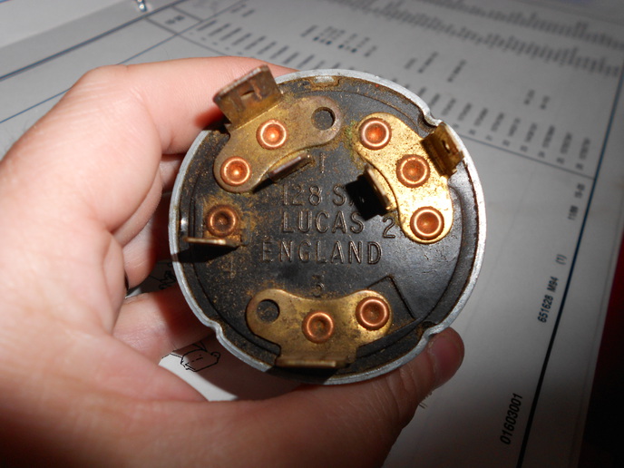
Included picture is the back side of my MF 261 ignition switch. Can anyone tell me what the wires attached to the 1, 2, 3, and 4 control/go to? I ask because the inner prong on #2 didn't have a wire on it at all and some of my wires look worse for wear. So this question is both for general knowledge and a bit of troubleshooting. (I didn't see this info in my manual or in my parts book.)

Thanks in advance!
a233808.jpg
 
Hello, my answer below is in response to a question posed by a reader to the 'Ask the Experts' pages in the UK 'Classic Tractor' magazine. Hope it helps.

A/ There is very little difference between the original and present replacement switches. The original 135 switch had a ?Heat-start?, ?Heat?, ?Off?, and ?Start? positions. Replacement switches have ?Off?, ?Ignition?, ?Heat?, and Start positions.

The wiring colours and original terminal numbers are;
Brown, bringing the 12V supply from the ammeter to terminal 1 of the switch.
Brown/green, terminal 2 going to the engine heater thermostart.
White/blue, terminal 3 going from the switch to the safety start switch and then changing to white/red to the starter solenoid.

The new switch will need to be connected as follows;
Brown - supply from the ammeter to terminal 1.
A supply to an amber beacon might be connected to terminal 2 for example
Brown/green to the thermostart from terminal 3
White/blue to the safety start switch from terminal 4

Low voltage electrical wiring is identified by a) the number of strands, b) the diameter of the strands and c) the cross-sectional area in square millimeters of the cable.
For example, a cable ? 14/0.30 1 mm? would be comprised of 14 strands of wire each one having a diameter of 0.30mm with a total a cross-sectional area of 1mm? and would be suitable for side and headlamps. An alternative to this standard is AWG ? American Wire Gauge.

Cable sizes for the above job should be;
Supply, brown 28/0.30 2mm? or 44/0.30mm 3mm?.
Thermostart, brown/green 28/0.30 2m?.
Safety start switch, white/blue 28/0.30 2mm.


Disconnect the battery. If you are replacing sections of the wiring identical colour coded wire should be used. Most colour and correct size wiring is available by the metre from specialist vehicle electrical component suppliers. Any corrosion on the old wires should be cleaned and new wires should be soldered in place. Connections should then be insulated preferably with heat-shrink tubing and the new section bound in tape or split plastic tube. New switches will normally require a smaller mounting hole than the original. A suitable packing washer can be used and the nut tightened or a coach washer filed to accept the new switch with its locating ?flat? can be riveted in place. If you are unsure of the wiring layout the probes of a voltmeter set to ?continuity? can be used to check for current flow in selected key positions.

DavidP, South Wales
 

We sell tractor parts! We have the parts you need to repair your tractor - the right parts. Our low prices and years of research make us your best choice when you need parts. Shop Online Today.

Back
Top