I'm sure someone has the answer for me....

nodollas

Member
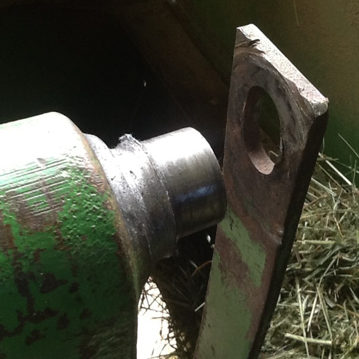
I have adjusted my lift linkage by the manual and the article that vintage tractor has. it goes smooth but, when done, and you push the position lever down, the control levers start to move in the direction of valve engagement. so with the position lever fully down and you start to raise the implement, the control levers actually move toward closing the valve first then as the position lever reaches the fast mark then the lift valve starts to engage and lift the arms. This doesnt seem correct to me. How far do you guys have to lift the position control before the arms raise??

Sorry for this long post but this is driving me nuts!
someone please help....
Thanks
 
Hi,
Forgetting the 'response' section at the bottom of the quadrant for the moment; Clearly the lift arms should raise when you move the position control lever upwards. When the linkage is fully down and you move the PC lever initially is there any response from the pump levers? They should be allowed to go into the 'pumping' position briefly before the PC linkage moves them back to neutral at your selected height. If this is not happening there would appear to be a loss of connection between the cam on the ram arm housing on the main shaft and the internal linkage. It is common for the rollers to seize and wear a flat on them and this looses the connection. The attached photo shows an extreme case. Check the linkage frame and rollers to ensure that all are straight and running correctly. Yes, it will mean removing the cover and almost starting from scratch but I think you have little choice.

DavidP, South Wales
a161426.jpg
 
Hello,
Yes, I have looked at your video several times. However without the engine running anf the 3-point actually lifting it is difficult to understand what happens where.

I think we need a little clarification on terminology here. When the pump is lifting the linkage it is generally referred to as the 'pumping' phase. As the linkage approaches the selected height it approaches 'neutral'.
And when lowering the linkage the pump is said to be in 'discharge'.

Do you have a genuine MF workshop manual? You mentioned that you have carried out the adjustments;
When required have you placed one or both quadrant levers in the exact place in their sector marks? If not the adjustments that you make have no reference point.
Have you carried out the adjustment of the Position and Draft levers?
Have you carried out the adjustment of the eccentric cam?
Have you carried out the adjustment of the control valve actuating lever?
Have you carried out the adjustment of the 'transport shut-off' and response limit stops?

Although more related to the Draft Control, have you checked for play in the control spring assembly? It is advisable to remove the assembly and tighten the spring if required EXACTLY as stated in the manual.

As you may be aware the system lowers the linkage as you move the Position Control lever downwards. This means that the control valve is placed in the full discharge position. As you approach the 'Response' section on the quadrant the control valve begins to return towards the 'neutral' position. It is this "closing of the tap" if you like, that gives the reduction in drop speed. At maximum 'slow' the "tap" is almost closed. The 'response limit stop should be set so that you cannot actually move the control valve into the 100% neutral position.

I still feel that the quadrant levers via the linkage are not 'communicating' correctly with the control valve lever.
Hope this helps.

DavidP, South Wales
 
David, thank you for your response... and the education on terminology. I understand now that I didn't provide enough detail as far as exactly which steps I had taken, or how. At the time of my (pleas for help lol) I had adjusted the position and draft levers, cam per the manual that I purchased here. The quadrant levers were exactly in their sector marks when I did this.

After adjusting the P & D levers I went no further as I didn't understand the movement of the P & D levers and there seems to be a specific order to the adjustment process. It seems what I didn't realize was, among other things, the "neutral" position thing or how the position control levers and lift arm position relate to one another and the control valve as well. The draft control spring was set before I re-installed the top cover(the first time).

As it turns out I let go of my reluctance to trust the shop manual and pressed forward. All of the adjustments are made and and everything is working as it should.

My frustration, I think, was not understanding how it (the lift) operated. It is not as simple as "pull up on a lever- valve opens- arms raise"

With help from this board and studying the manual I have, at least, a better grasp of how things work with the lift.
Sorry for the long rambling post and thanks again .
David R
 
Hello DavidR,
Hope you have the operation understood now. One final very important setting is the lift arm height. Without this set correctly it is possible to 'lock up' the system under hydraulic pressure.

Remove the hinged pin from the rear of the centre housing. Place a length of 3/4" or 19mm bar into the centre housing with one side protruding enough to be under the horizontal pins at the top of the lift rods. Start the engine and raise the Position Control lever until a distance of 11.8" is achieved from the centre of the lift rod pin to the centre of the bar you have fitted. Move the Position Control stop up against the PC lever and tighten it. This gives maximum lift without any fear of a lock-up. You may lose some lift height. Check the bolts/bushes between the bottom of the lift rods and the lift arms.

Regards

DavidP
 

We sell tractor parts! We have the parts you need to repair your tractor - the right parts. Our low prices and years of research make us your best choice when you need parts. Shop Online Today.

Back
Top