MF 165 Hydraulic problems

MikeNL

Member
I think the pump is ok because the loader lifts well, but I have always felt that my hydraulics weren't working right and when I tried using a plough the depth control raised and lowered but was not responding correctly.
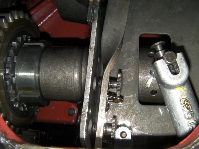
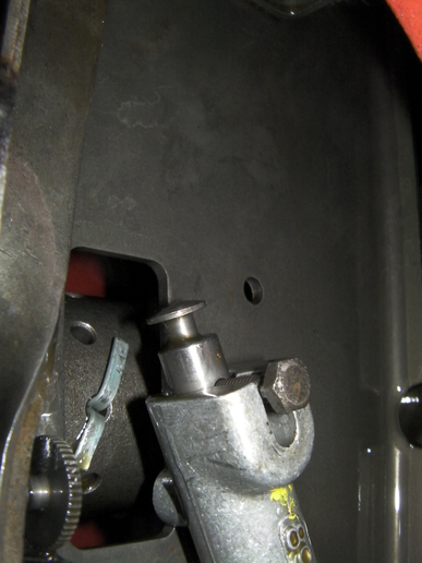
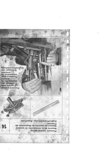
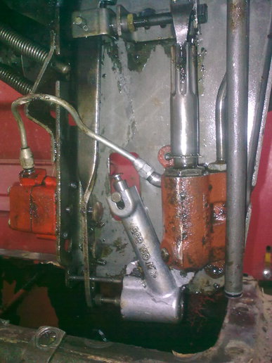
Suspecting the control spring adjustment I removed it to check. Even with a self made tool it took a lot of time and ingenuity to get it out. I think the adjustment was ok, but it wasn't a waste of time as I could fit a new rubber.
My 135 also has pressure control and if I raise the drum mower and move the lever past constant pumping into pressure then it can be lowered, held or raised according to the pressure.
My 165 raises using position (sounds like it's working hard with a round bale on a pallet!) but if you go past constant pumping it does not lower again.
Another symptom is that when the diverter valve is switched to the loader, the link arms slowly sink under the weight of the counterweight.
I have never had the cover off this tractor, although I fitted new top O rings when I changed the diverter valve.
The next step is to have a look inside, but any tips on what to look for which would help to avoid removing the cover would be appreciated.
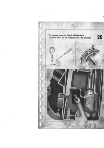
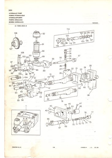
I have kept a lot of notes on adjustment and I have the MF27 manual but I do not have a pressure guage.

Mike.
 
Hello Mike, how are you?
Taking your posting in stages;
The control spring plunger should be tightened until the spring is stiff to turn by hand. When checking this insert a punch or thin screwdriver into the pin hole so that it does not tighten.
When adjusting the control spring nut the DRAFT lever must be in the fully lowered position. Adjust the nut until endfloat just disappears. Any further and it will reappear.
When you go into the PRESSURE CONTROL part of the quadrant and cannot lower the lift arms, do you have any implement attached or just the empty arms. Pressure Control will vary the pressure from about 500psi to blow-off pressure. The system cannot work at zero pressure when in PC low. This pressure is around 1/6th of the available pressure. It takes far less than that to lift the empty linkage. 500psi was enough to lift my concrete counterbalance!
When the divertor valve is switched to the loader you have effectively sealed off the 3-point lift circuit. There may be some leakage past your DV but the bulk will escape past the seals/rings in the lift cylinder. This is quite normal unless it is falling in less than 3 to 5 minutes.
Partly drain the oil and remoce the RH side cover. Reaching inside and upwards you will find the PC adjuster barrel. It has quite sharp 'teeth' around the outside at the lower end. Do not turn it but check that it moves up and down when you operate the PC lever. The action is to increase the load on a spring and valve inside the housing.(When in the POSITION CONTROL quadrant the spring remains fully compressed at its adjustment.
A pressure gauge would be a good investment as you will need one if you carry out the adjustment sequence. You will require a gauge to read to at least 3500psi.
Hope this helps. Let us know.
DavidP, South Wales
 
Hi David , thanks for your reply.
I tested the system with a round bale on pallet forks (about 300kg).
I did'nt want to spend much time on this job , so I raised the loader, put the right wheel on a concrete block and took the cover off without removing the foot plate.
I was having problems feeling around for the adjusting tube so I took some photo's.
They say a picture is better than a thousand words and these pictures say a lot.
Although I like things to be "in order" and origional, the tractor is mainly for the loader so it's not such a problem. The lift works and goes high enough to latch the pickup hitch.
It does however raise a few questions with respect to a relief valve, which assume is fitted.
The lift is not as strong as my MF155 which has the same back end so I was wondering if, as you said, some oil is leaking past the ram cylinder or the relief valve has a lower rating.
I have heard of this being done and with your experience I'm assume you have also seen such a modification. If so can you let me know if there are things I should check.
Mike.
a125395.jpg

a125396.jpg
 
Hi Mike,
You have mentioned that your tractors have Pressure Control fitted. The latest photos posted are of a tractor without PC. No PC body, pipe or diaphragm are shown. The two attached pages from the MF Hydraulic Adjustment manual show the components and the setting barrel 'A'.
I have deliberately printed the first picture upside down to make it easier to see the components. This was originally taken when the hyd cover was upside down. The position of the barrel when the quadrant lever is fully lowered in the PC quadrant will give initial maximum pressure. The second image shows final adjustment being made. On PC tractors this is the relief valve so the barrel should be adjusted to the correct pressure for the tractor. Non-PC tractors have a conventional relief valve screwed into the pump body.
DavidP
a125611.jpg

a125612.jpg
 
Thanks for the pictures. They're better than the ones I had. That's what I meant by a picture (photo) telling the story.
When I could'nt feel the adjuster tube I compared it with this photo of my 135 which I took when I had it open.(
Then I understood why I could'nt find it. - It's been removed!
I assume the previous owner who used the tractor for "hauling taties" had problems and chose to have it removed instead of paying to have it fixed.
Is it possible that a relief valve has been fitted to the original pump or would the pump have to have been changed as well?
I borrowed a guage yesturday and although I did'nt have the right adaptor I managed to quickly measure the pressure at just over 2500 on constant pumping before spilling too much oil.
a125709.jpg
 
Hi Mike,
As my late father used to say "I see it all now....some of it".
If the PC has been removed then that would explain it. If you look at item 84 on the attached parts page that is the relief valve which screws into the upper right hand corner of the back plate of the pump.
It is cylindrical, about 5/8" (16mm) in diameter and about 2 1/2" (60mm)in length. You should soon be able to see or feel it.
With the PC components removed the PC control lever will have no effect in the PC quadrant. You will have full hydraulic pressure as expected in the Position Control quadrant.
The pumps are the same, the PC one has a plug in place of the RV.
2500psi is correct essentially for round rear axle tractors.
DavidP
a125734.jpg
 

We sell tractor parts! We have the parts you need to repair your tractor - the right parts. Our low prices and years of research make us your best choice when you need parts. Shop Online Today.

Back
Top