135 hydraulic linkage. Not funny any more.

witzend

Member
Come on you 135 experts, DavidP where are you?

I've been doing this check procedure from DavidP. (Draft control in the rearmost position throughout):
First of all position the hydraulic cover upside down but in a position where the upper lift arms can be lifted by hand and lowered. Have an assistant to hand to move the upper lift arms.
Tell the assistant to hold the upper arms up..in effect in the lowered position when fitted. Move the Position Lever into the lowered position. The vertical lever should now be pushed forward (as in fitted position) to put the control valve in the 'discharge position.
To recap if the cover were fitted; the position control lever is down, the 3-pt is down and the vertical lever is leaning forward. Exert gentle pressure rearward on the vertical lever but not enough to move it.
Now raise the Position Control lever slowly. The vertical lever will move rearward (as if fitted) through the neutral position and into the pumping position. Leave the PC lever at about halfway. Tell you assistant to lower the upper lift arms slowly (raise them when fitted). As the upper arms approach the selected position of the PC lever the vertical lever should move into the neutral position. If it does this it is working OK. You will probably need to do this quite a few times to firstly understand how it works and the relationship between the PC lever, upper lift arms and vertical lever position.
If you are able to support the hyd cover right way up it will be a lot easier.
The position control feels fine, the vertical lever goes backwards and forwards, UNTIL the lift arms are raised (the lowered position in normal life), then it seems like it's disconnected. Tried it with the draft control in the frontmost position and it just flicked back. I reckon everyone must be getting pretty sick of this, so thanks everyone who's taken a look. I'm stumped and wondering where to go from here.
 
Hi, not deserted you, not on comp yesterday.
Do you have the hydraulic cover upside down? If you do it is difficult to understand the movement in reverse.
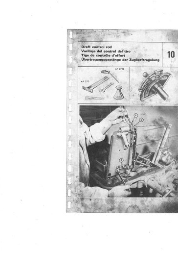
The photo shows the support bracket which fits into two of the holes on the rear of the cover. At the top end is a small pulley. A cord with a hook on it hooks onto the bottom (right way up) of the vertical lever. At the other end of the cord are weights. These must be 3 lbs. Any more and the loading will be upset. Three pounds is the pressure exerted by the pump lever so that you can simulate the cover being in place.
With the cover upside down and position lever in the 'down' position, lift the lift arms upwards to simulate the 3-pt being 'down'. The vertical lever should now be fully away from the lift cylinder. Move the PC lever to a point about halfway. The vertical lever should now move towards the lift cylinder fully. Allow the lift arms to fall slowly (as if rising). At about halfway the vertical lever should move to the central position and stop. Raise the PC lever fully and again the vertical lever should move fully towards the cylinder. Lower the lift arms fully and it should move back to the neutral position.
Lower the PC lever, the vertical lever will move fully away from the cylinder until you raise the lift arms (as if lowering) until the vertical lever returns to neutral.
Hope you can follow this. It is essential to rig up something in the way of a support bracket with weights to help you understand what should be happening.
Once you understand how it should work, hopefully you will see where the problem is.
Let us know how you get on.
DavidP
a78191.jpg
 

Ta Dah! Look, no hands. After 2 hours of fiddling, I mean careful adjustment, I (kind of) understand what's going on and how the bits work together. And more to the point I have a working position control and a usable tractor at last: check the photo. Result.

I did not find that very careful following of the manual either made complete sense or worked very well. What's the point of giving a clearance of .004" when the result totally depends on where the control lever is placed within a range of several inches? I found it more fruitful following DavidP's instructions (for which many thanks) and working out what was meant to be happening and adjusting accordingly.

Only problem at present is the Draft control now doesn't work very well. The lever won't hold it's position and keeps springing upright. Any thoughts on what I've mucked up?


9772.jpg
 
Very pleased for you. You are a man of some perserverance.And Dave"s a real star.
The draft lever is held in place by simple friction against the quadrant. There should be a screw and a spring and a washer or two.Tightening the screw increases the friction.On worn models with weak springs there can be issues about the screws fouling between draft and postion levers but simple ingenuity(or new springs) will overcome it. Nothing for a man of your talents!!!!!
 
(quoted from post at 09:14:53 08/05/12) PS You don"t need the draft lever with the grass topper. It should always be at the up position.

Thanks for the info on the draft control: "worn model" certainly covers the situation here – not just the tractor – so now I know there's not a serious issue with the draft I'll leave it for a winter w/e.
 
Hi, great news. The 0.004 is necessary to ensure that no excessive gap or pressure is present which might affect the system operation. Well done.
DavidP
 

We sell tractor parts! We have the parts you need to repair your tractor - the right parts. Our low prices and years of research make us your best choice when you need parts. Shop Online Today.

Back
Top