
bstogsdill
New User
This message is a reply to an archived post by Osage on August 19, 2009 at 12:24:18.
The original subject was "Wiring Diagram JD 1010".
Hi-
I tried to create a wiring diagram for my 1964(?) 1010 RUS.
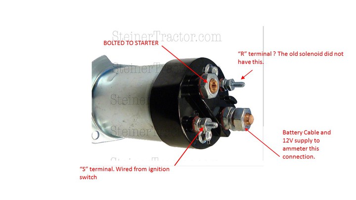
Also, I purchased a new starter selenoid and it has 4 terminals in stead of 3 terminals. NOt sure what to do with the extra terminal...
Fighting with Autocad how to create a Jpeg to post my full schematic.
My new starter selenoid has 4 terminals... 1 battery and ammmeter voltage conection, 2 the starter motor, 3 "S" terminal, connected to ignition starter switch, and 4 "R" terminal.. for which i have nothing to connect. The instructions sat connect "R" to relay or resistor.
My Voltmeter also broken so i could not see how selenoid is wired internally. I think the battery and starter contacts are closed when it is engaged and
I assume the S terminal when powered should charge the coil, but does the R terminal need to go to ground to complete the circuit?
Thanks
BS
The original subject was "Wiring Diagram JD 1010".
Hi-
I tried to create a wiring diagram for my 1964(?) 1010 RUS.
Also, I purchased a new starter selenoid and it has 4 terminals in stead of 3 terminals. NOt sure what to do with the extra terminal...
Fighting with Autocad how to create a Jpeg to post my full schematic.
My new starter selenoid has 4 terminals... 1 battery and ammmeter voltage conection, 2 the starter motor, 3 "S" terminal, connected to ignition starter switch, and 4 "R" terminal.. for which i have nothing to connect. The instructions sat connect "R" to relay or resistor.
My Voltmeter also broken so i could not see how selenoid is wired internally. I think the battery and starter contacts are closed when it is engaged and
I assume the S terminal when powered should charge the coil, but does the R terminal need to go to ground to complete the circuit?
Thanks
BS