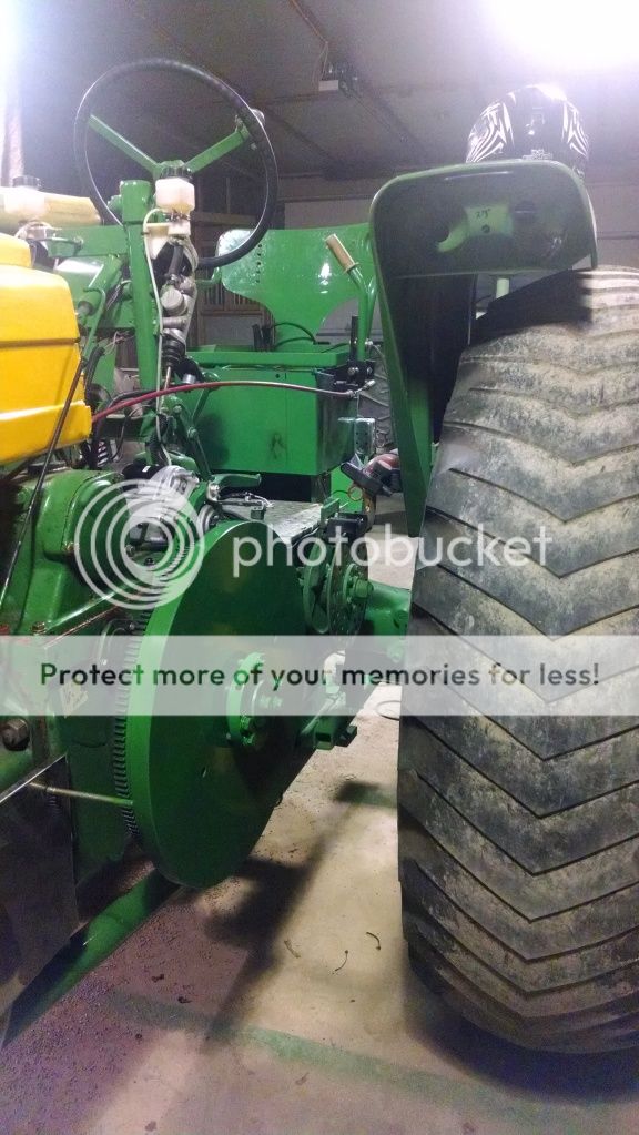
How are flywheels balanced?

Are flywheels balanced only in relation to themselves (like a tire) or in relation to the crankshaft and in the case of two cylinders the pulley?
The reason I ask is that occasionally in cases of engine transplants or conversion the tractor might end up with two flywheels. This last summer I talked to a guy who put a V12 GM in an M Farmall. He told me that it still had the M flywheel and clutch in it. Somehow I never got around to asking him if that messed up the balance of the engine.
 
I imagine only to themselves. When I put an 855 Cummins in a 2470 Case, I had the butt of the crank machined to accept the Case 504 flywheel.
 
Good Morning Richard, long time no see, as you know Electricity (NOT Mechanical) is more in my line, but as far as I know, in the old Two Cylinder Deeres, the balance is as follows:

The overall side to side balance consists of the Flywheel, Crankshaft, and Clutch Drive Disk. And, of course, the rods and pistons and entire assembly must be balanced. When one piston and rod is going one way, you want the other piston and rod going the other way to be in balance.

The Flywheel itself is purposely OUT OF BALANCE with that heavy counterweight on its one side. Over on the other side, the Clutch Drive Disk is also purposely out of balance, but its heavy counterweight side is (if both are timed properly on the correct crankshaft splines) is exactly 180 opposite from the Flywheels heavy side. That reduces cross harmonic vibration or something like that ???? (have to ask the mechanics).

If a clutch drive disk (or Flywheel) is removed and NOT installed back onto the correct crankshaft spline such that its heavy side is NOT 180 opposite from the flywheel, THAT CREATES A MAJOR OUT OF BALANCE VIBRATION.

So I cant tell you how to balance the Flywheel other then its NOT balanced in and of itself, its much heavier on one side and that's obvious if you look at how its made. Similar, the clutch drive disk is NOT balanced and has an obvious one heavy counterweight side which must be 180 opposite from the flywheels heavy side.

See what the mechanics have to say, toss me an electrical question next time lol

Hey a man of your stature should already know this!!! You just testing us lol but I must assume you're already well aware of all the above, just asking about how to balance an out of balance flywheel maybe??? Hope someone can tell us

John T NO Warranty, but I think the above is true, Ive been wrong before lol
 
From what I know the Waterloo JD tractors (2
cylinder) flywheels were balanced to their
respective crankshafts at the factory as an
assembly. I'm thinking that the clutch driver
wasn't included in this as they were all machined
to spec (should be the same in terms of balance).

Somewhere I've seen a video (probably on the JD
day historical videos) which showed this process
at the factory.

The next engine I do on a Waterloo tractor, I plan
to have whole engine balanced...probably more $$
but I want a super smooth (no vibration in the
fenders such as on my 630). My 720 diesel has more
engine vibration that I would prefer...but I keep
telling myself it's all the extra power under the
hood :)
 
The clutch driver was included in the balanced assembly IF the crankshaft was not internally balanced. On tractors that were internally balanced (with counterweights) the driver was not balanced. I always balance the rods and pistons to each other any time I have one of these engines apart. You would be surprised how much they can vary. If the rods match, and the pistons match, the engine will be very smooth. I did this on my 70 pulling tractor and also statically balanced the crankshaft and flywheel. She's smooth as silk. Mike
 
Yeah...If it weren't such a pain, I'd pull by 720D engine back apart and get it balanced like that. It probably needs mains as I didn't replace them when I overhauled the upper engine (new rods but left mains and crank in the tractor...).

If I get to do the engine on my 630 sometime, I will definitely have everything balanced for that smooth as silk effect.

Tyler
 

I realize that on two cylinder Deeres the flywheel and pulley must be balanced in relation to each other.
We've had a few articles over the years about guys who have cut their crankshaft and re-welded it so the tractor would fire 180º apart. They really had to do some serious re-balancing.
I haven't done a lot of out of frame overhauls on 4-6-8 cylinder engines, but on the few I have I thought that there was always a locator pin so the flywheel could only be put on one way, but then I suppose that might just be to keep the timing marks where they should be.
Many years ago JR Hobbs and I had this idea for a top secret project, the heart of which would have been two LUC engines stuck together to make a four cylinder flathead Deere engine. We wondered if it would be balanced with just one original flywheel.
 
I personally think you are perfectly correct, John, about the counterweighting of the flywheel/clutch driver. I do have a question , tho, as far as one wanting to "smooth out" an existing tractor without taking it apart. They have to be pretty darned close as is, so what would keep one from experimenting with small 1" cube magnets on the flywheel to get it that last percentile of balance to eliminate that minor amount of fender shake. They can't be that far off or they wouldn't have lasted this long. What say you??
 
I'm just not that sharp on this subject, If a magnet could fine tune the balance and then be epoxy or glue attached so it never moves I guess that will work. What I don't understand is the method and mechanics to ever even measure then accomplish this in the first place, how to balance such big heavy bulky objects?????

Outa my pay scale lol

John T
 
Over the years I've seen several John Deere G's and a few A's in dead weight pulling using two flywheels sandwiched together. Having some idea of how the engines are balanced with the flywheel, crankshaft, rods, pistons and clutch driver as a unit, it seems the engines with two flywheels would be seriously out of balance. Well, if they are, they seem to take it okay....Hmmmmm, I wondered....Always seemed to me that double flywheel could snap the splined end right off the crankshaft. but I've never seen it or heard of it happening.
 
I think ,first of all, that one would have to make some assumptions. One being that the factory counterweights are , in fact, correctly located and that they are just not the exact correct weight. Given that then one would only have to experiment by locating magnets either on the factory heavy side or 180° to the other side. Depending on how much ones fenders shake it might only take 2 or 3 oz to at least show whether you were gaining or not.Then one could add more or less to get desired results. If they were placed on the inside of the flywheel then they would stay at least for the experiment and then could be epoxied in place once one achieved success. Balancing (IMO) is like in an automotive application where all the reciprocating parts are made the same weight and all the rotating parts are spin balanced with the appropriate "bob weights" attached to simulate reciprocating parts so when all is assembled it will all be a balanced assembly. What we are talking more about here would be (IMO) called counterbalancing or the cancelling out of uneven power strokes. All that weight isn't on that flywheel because something inside is made wrong or something is out of tolerance. So since we are talking counterweighting the power strokes , we are never going to be perfect since "power strokes" is a variable , but we might get rid of the fender shake by adding a little one side or another. I'm a pretty "frugal" person by nature but am I full of BS too? Open to anyones thoughts. RB
 
Any engine sporting a harmonic balancer on the front of the crankshaft can be used with an existing flywheel as long as it has enough mass to counteract vibrations caused by the engine operation.
The example above lists the original M flywheel was used. A clutch type flywheel has enough mass ( weight) to counteract most vibrations caused by operation up to limited RPMs in such an in-line configuration.
I am sure the M flywheel was static balanced prior to installation, I am unsure of how many RPMS the repower engine would be governed at, but in this instance, considering an M's drive train, I am sure it would be lower than it's original installation in another vehicle.
 
I have replaced the flywheel on my 44
B with one from a similar tractor--never had a balance or vibration problem. The clutch drivers for the early B engine(4-1/4x5-1/4) look the same as ones for the later(4-1/2x5-1/2) engine, but with a different part number. I suspect the difference is in the balance weight portion of the casting. One of the old JD movies showed pistons being matched in weight on a balance scale. Actual weight didn't matter, just so they were the same. One claim made for aluminum pistons was reduced vibration. Many, many cast iron pistons were replaced with aluminum, obviously much lighter, without rebalancing any engine components. So go figure!!
 
Getting a 2 cylinder engine balanced is a waste of money most of the time because most engine builders do not know how to correctly balance a 2 cylinder engine, the same tricks and rules of conventional engines don't apply. I have actually seen a tractor shake worse after being balanced at a professional engine shop. I've actually balanced a few 2 cylinders myself, it took a while to figure out how to do it but it's not that hard. A diesel by it's nature will never run as smooth as a gas unless it's a very weak diesel...I've been there before.

The 2 cylinder crank in itself is balanced better than most think. The crank in my pulling tractor is static balanced and I machined a billet flywheel and clutch assembly which did not require any weights. It actually runs pretty smooth for as much compression as it has.


We sell tractor parts! We have the parts you need to repair your tractor - the right parts. Our low prices and years of research make us your best choice when you need parts. Shop Online Today.

Back
Top