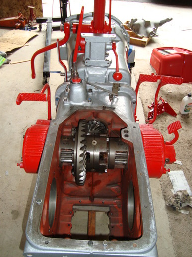
here is what Fred is talking about
Ring gear and pinion tooth pattern interpretation
When setting the pinion position, many of the service manuals required a final pinion position check by using gauges that verified the dimension from the center line of the differential carrier (center line of ring gear) to the face of the pinion (button). This surface (button) is not used on all new gears for verifying the pinion position. The service tools will be used to establish the proper amount of shims required prior to installing the pinion gear. The final pinion position will be verified by using the GEAR CONTACT PATTERN METHOD, as described in this bulletin.
RING GEAR AND PINION TOOTH CONTACT PATTERN
toothcontactpattern_large.jpg
The TOE of the gear tooth is the portion of the tooth surface at the end towards the center. The HEEL of the gear tooth is the portion of the tooth surface at the outer end. The TOP LAND of a gear tooth is the surface of the top of the tooth. Every gear has a characteristic pattern. The illustrations show typical patterns only, and explains how patterns shift as gear location is changed. When making pinion position changes, shims should be changed in the range of .002 inch (.05 mm) to .004 inch (.10 mm) until correct pattern has been obtained.
When a change is backlash is required, backlash shims should be changed in the range of 1 1/2 times the amount of backlash required to bring the gears into specification. For example, if the backlash needed to be changed by .004 inch (.10 mm), the shim pack should be changed by .006 inch (.15mm) as a starting point. The actual amount of backlash change obtained will vary depending upon the ratio and gear size.
High backlash is corrected by moving the ring gear closer to the pinion. Low backlash is corrected by moving the ring gear away from the pinion. These corrections are made by switching shims from one side of the differential case to the other.
NOTE
When making changes, note that two variables are involved. Example: If you have the backlash set correctly to specifications and you change the pinion position shim, you may have to readjust the backlash to the correct specification before checking the pattern. Refer to pattern interpretation.
WARNING: Gear teeth may have sharp edges. When handling gears, use care to avoid personal injury.
STEPS:
(1) Paint ring gear teeth with a marking compound to both the drive and coast side.
(2) Rotate ring gear one complete revolution in both directions while load is being applied with a large screwdriver or simular tool between the carrier casting and differential case flange.
PATTERN INTERPRETATION (RING GEAR)
Driver Side................Coast Side
Heel Toe.....................Toe Heel
ringgearinterp1-large.jpg
Normal or desirable pattern. The drive pattern should be centered on the tooth. The coast pattern should be centered on the tooth, but may be slightly toward the toe. There should be some clearance between the pattern and the top of the tooth.
ringgearinterp2_large.jpg
Backlash correct. Thinner pinion position shim required.
ringgearinterp3_large.jpg
Backlash correct. Thicker pinion position shim required.
ringgearinterp4_large.jpg
Pinion position shim correct. Decrease backlash.
ringgearinterp5_large.jpg
Pinion position shim correct. Increase backlash.
PATTERN MOVEMENTS SUMMARIZED
(1) Decreasing backlash moves the ring gear closer to the pinion.
Drive pattern (convex side of gear) moves slightly lower and toward the toe.
Coast pattern (concave side of gear) moves lower and toward the toe.
(2) Increasing backlash moves the ring gear away from the pinion.
Drive pattern moves slightly higher and toward the heel.
Coast pattern moves higher and towards the heel.
(3) Thicker pinion position shim with the backlash constant moves the pinion closer to the ring gear.
Drive pattern moves deeper on the tooth (flank contact) and slightly toward the toe.
Coast pattern moves deeper on the tooth and toward the heel.
(4) Thinner pinion position shim with the backlash constant moves the pinion further from the ring gear.
Drive pattern moves toward the top of the tooth (face contact) and toward the heel.
Coast pattern moves toward the top of the tooth and slightly toward the toe.
Untitled URL Link