Ford 4630 Charging Question

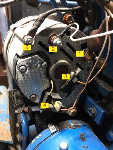
Just bought a Ford 4630. Low hours but been sitting for years. Got it running great but having trouble with charging system. Charge light is on with key on, engine off as it should be. With engine running, charge light is off sometimes, on other times. Voltage while running is 12.44v, same as battery with engine off so it is not charging. Voltage at alternator is 12.44v as well. I do feel a slight magnetic pull on a screwdriver at the back of the alt but it is only slight. Again, this tractor sat for 5+ years uncovered with the hood off so the alternator was rained on a lot. Anyway, have attached a photo below with all the wires labeled to ease the discussion. It might be a bad alternator I realize but I want to know for sure before I start throwing money at it. I bought a full set of OEM Ford New Holland manuals but the schematic for the charging circuit is so small I can't even read the wire colors to help me troubleshoot. Could you guys please use the photo attached with labeled wires to tell me specifically how to test my alternator on my tractor as well as confirm it is wired correctly? I know the previous owner and the alt alledgedly charged fine when the tractor last ran so I assume it is wired correctly but need to confirm so I can get this great tractor back charging again. Thanks for any help you can offer guys.
a178297.jpg
 
1) output
2) tach
3) warning lamp
4) battery temperature sensor (always suspect)
5) ground
 
Thank JMOR I should have added that I already removed the battery sensor plug and placed a jumper wire in it. Should it be done with a jumper wire or left open?
 
Also the tach wire confuses me. This tractor like every older ford I've worked on has a mechanical tach so why a wire from the tach to the alt?
 
First thing I'd suspect is worn or sticky brushes. Remove the 3 screws holding the regulator on ad remove it - brushes will be attached. The two slip rings inside should be bright shiny copper. Dull and black means no contact. If these parts look good, put back together, start engine, and insert a screwdriver in the slot just behind the regulator. This should cause the alternator to charge at max capacity. If voltage goes up, suspect bad regulator or temp sensor circuit.

As for the battery temp sensor circuit, leaving it open definitely will cause a no charge issue. I don't believe shorting it is the right way to go either. Info I have suggests testing a temp sensor by substituting a 205 ohm resistor in its place.

Tach terminal is meant to drive an electronic tach. Should be no use for that wire on your tractor.
 
I'm not very knowledgeable about those systems with the battery temp sensor, but I believe I remember someone posting that to bypass them you need to do so with a resistor of a specific value, as merely jumping the wires together wouldn't work.... but then again, my memory seems to be getting worse the older i get so I may be mistaken on that. Hopefully someone who knows more about it will jump in and either confirm or correct what I have said.
 
Bern, I will remove that plate this weekend and look. Assuming the slip rings look shiny and parts look good I'll put back together and insert my screwdriver in the slot in the back of the alternator closest to the regulator? Is this the slot closest to the number "2" I have marked on my diagram?

Also, interesting point about the temp sensor circuit. I had no idea leaving it open or shorting it out isn't the answer. I assume I can purchase a 205 ohm resistor at the auto parts store, wire it in a "jumper" wire then use that jumper wire to short the plug that was typically at the temp sensor?

The tach terminal confuses me completely. My tractor has a mechanical tach. Mine is an open tractor (no cab). I assume cab tractors had electronic tach I've just never seen one. Anyway, no telling why my tractor has a wire terminated as this tach terminal. I assume I should just unhook that wire and see what happens?

Thanks for all of your help guys.
 
I do not believe that the resistor is a particularly critical value, as the sensor resistance value varies with temperature, as that is what make it function. You are not likely to find a 200 or 205 Ohm resistor at auto parts store. Try electronics supply stores. Since Radio Shack is gone, perhaps Fry's or similar or Mouser. Standard resistors in that range would be 180, 200, 220.
Bern is absolutely correct (& he doesn't need me to say so) in that an open/disconnected sensor will kill charging. I am not so completely sure that a direct battery to temp sensor input at alternator would be a problem (same as shorted temp sensor). i.e., may charge just as well as with good temp sensor? Haven't tried it.
 
Understood on all account JMOR. I'm going to remove the plate to make sure all looks clean and operational, leave the jumper I have in now at the temp circuit, probe the screwdriver in the slot Bern talked about to induce charging and go from there. I will also unhook the wire at my tach post since my tach is mechanical. If not charge I will consider the resistor in the temp circuit as discussed. You guys helped me out. Let me get to work this weekend. JMOR, can you conirm which slot exactly Bern was telling me to insert the screwdriver in by referencing my attached photo?

Thanks.
 
JMOR where did you get that diagram. Says "A127" I just wonder if it came from an original Ford Manual. As I stated in my original post I did the good deed of buying the entire set of OEM
Ford manual for this tractor and the stinking electrical diagram is so small I literally cannot read the wire colors with a magnifying glass. My 12 year old daughter with great eyes can't see it either - no joke! As much as I paid for this stack of manuals and the electrical diamgram for the engine isn't legible...
 
(quoted from post at 13:32:42 11/17/17) JMOR where did you get that diagram. Says "A127" I just wonder if it came from an original Ford Manual. As I stated in my original post I did the good deed of buying the entire set of OEM
Ford manual for this tractor and the stinking electrical diagram is so small I literally cannot read the wire colors with a magnifying glass. My 12 year old daughter with great eyes can't see it either - no joke! As much as I paid for this stack of manuals and the electrical diamgram for the engine isn't legible...
think it was from one of Bern's postings. Where does the jumper wire you have now jumper from & to?
 
There is a factory 2 prong plug harness up close to the battery
tray that the sensor plugs in to. I simply unplugged the sensor
and jumped a wire from one prong to the other on the alt side
of that harness plug.
 
As others have mentioned the resistance should not be critical. I worked in electronics service and repair for a number of years. 180 or 220 ohn resistors would be very common, 200 maybe/ maybe not.

Also, those resistors likely have a plus or minus 5 or 10 percent tolerance value. Thus when actually measured, they they could be 5 or 10 percent above or below the indicated value.

A 100 ohm resistor would be very common. Connected in series (end to end) the resistance values add so you could put two 100 ohm resistors in series and get 200 ohms
 
As often as those expensive temperature sensors seem to come up as the problem child, I wish I had one so I could measure it at room temperature, in ice bath and in hot (175-200 degree) bath. Maybe (hint, hint :wink: ) someone will.
 
JMOR I'll measure it for the group to see what I get at ambient, cold and hot temps just so we have an idea. I am assuming a resistance reading at each will tell the story?
 
(quoted from post at 16:31:26 11/17/17) JMOR I'll measure it for the group to see what I get at ambient, cold and hot temps just so we have an idea. I am assuming a resistance reading at each will tell the story?
Great. As long as you are measuring at that connector, you ought to measure voltage at the two wires coming from tractor harness. One (probably female) should be battery voltage (key on/off, not sure).
 
FWIW Got me curious.

On my 1992 5610 Series II, I connected ohmmeter (cheapie digital) between sensor connector at alternator and charge output. (wiring diagram shows that as circuit through temp sensor). Read bottom of battery tray near the sensor with a temp gun and at 52 degrees the ohmmeter read 223 ohms.

Tried to warm with a heat gun, but with loader in the way I couldn?t get a stable reading. It did appear that resistance dropped as temp increased. I know this is an incomplete experiment, but does indicate to me that a 200 ohm fixed resistor should be in the ball park.
a178346.jpg
 
Makes sense to me that as sensor resistance decreases (hotter batt temp), that input voltage to internal regulator circuit will increase, thus reducing alternator output. In a lead acid battery, the charging rate should be reduced at hotter temperatures.
 
I cleaned the brushes with Emory cloth although they looked good. Added a new battery since I have been borrowing one of another tractor of mine and she appears to charge fine. Battery at 13.4v charges at 14.5v just off low idle. Only thing is most times at low idle my charge light is on but any speed higher than low idle the light goes out. Is this normal?
 

We sell tractor parts! We have the parts you need to repair your tractor - the right parts. Our low prices and years of research make us your best choice when you need parts. Shop Online Today.

Back
Top