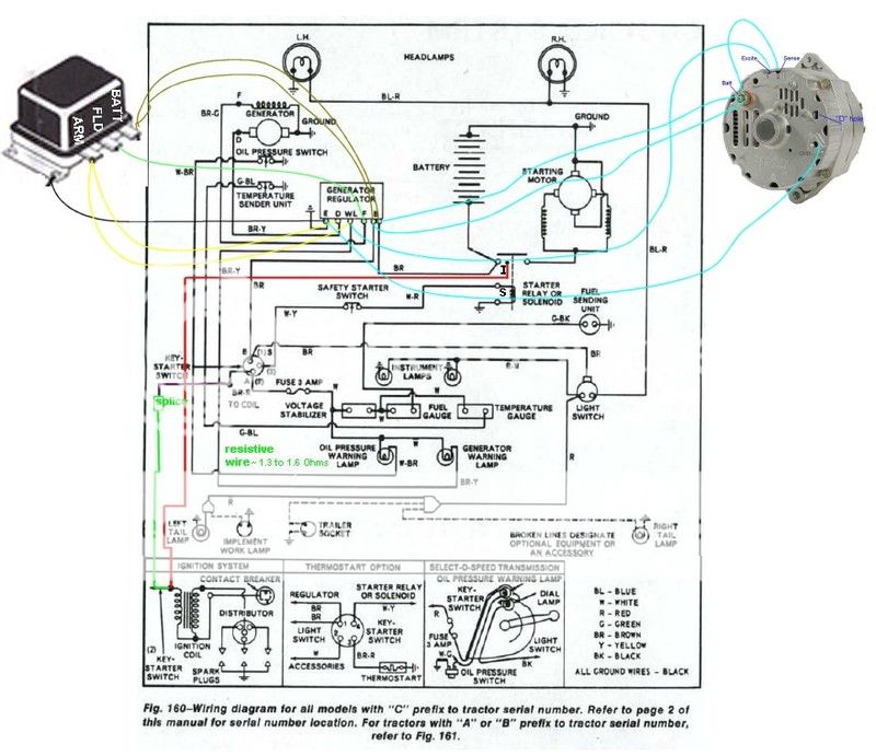
First off, I do apologize for the confusion my last threads caused and thanks to Jmor for the help up to this point. I have attached the wiring diagram for my tractor for reference. I purchased this
kit to take place of my current 12v generator http://www.yesterdaystractors.com/Ford-4000_12-Volt-Conversion-Kit_6X10300ALTH.html. As advised by Jmor I have removed the A and F wires from both the
generator and regulator. Which leaves me with a ground at the generator and regulator and the B wires at the generator. I intend to splice the B wires together and this is where my question starts.
With the new alternator, I was given a wire harness that has a plug that goes into the alternator and has a red and black pigtail. Per the instructions, I will connect the red wire from the plug to the
battery stud on the alternator. I assume I need to run a wire from the B wires back to the alternator but where does it connect from there? I am guessing the battery stud on the alternator? Does that
mean the black is a ground? Thanks again for any help the instructions provided with the kit were not for the same style regulator as mine. Also for those wondering, I fabricated a new bracket for the
alternator so it would mount correctly.


