1 wire alt update

henryv11

Member
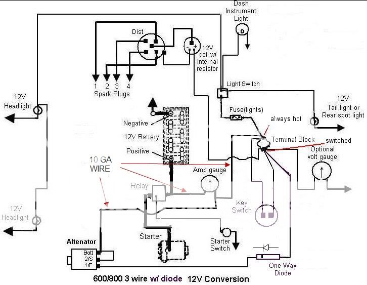
Thanks to all who helped me. I got it charging ok now. I jumpered the F term to batt stud
at alt ran large wire from alt to load side of amp meter along with lights ran wire from
sol where batt connects to other side of ammeter. the amps drop off right away after start
up. Only thing you have to rev it up a little at first to get it to charge. SOme guy named
SOund Guy told me to run wire from R term on alt to key sw but I cant get at it right now
maybe that would help He said it would make a 3 wire out of it. Sorry for asking so many
dumb questions but I feel more confident now. We all cant be as smart as others.Thats what
makes the world go around.
 
I'm finding it difficult to believe that you can't get to the switched side of your key switch at all. Seems as there should be a wire running to the primary of the ignition coil, providing power to run. Are you saying you can't get to the wire running to the ignition coil, or the coil itself?

Electrically the same to come off the back of the switch, or the end of the coil if only wire inbetween.

In that excite wire, add a 194 lamp inline, or as momentary push button like an add on horn button with isolated terminals. Startup, then hit the switch for a second.
 
1) You should refer to the small terminals as #1 and #2. The R and F; sometimes two R's and one F; sometimes F and S; are all cast into the case so this case can be used in other applications.

2) One wire alternators are very expensive. I suspect you as most were sold a 3 wire alternator that they were calling a 1 wire alternator. Makes for a easier sale to the electrically challenged. It works as you have found out; on a principal of electrical leakage; but takes high RPM's to get it working.

3) The #2 terminal (what you are calling F) is the remote sensing terminal. The wire is suppose to run deep into the electrical system to measure voltage drop across the system wires. The alternator is suppose to put out 14 volts. If this #2 wire reads 13 volts or 15 volts it tells the alternator to either increase or decrease the output to maintain the 14 volt output into the system. In a car with lights; stereo; power windows and door locks it is a critical wire. For a tractor with minimal wiring just jumping it the Battery terminal on the back of the alternator is fine.

4) The #1 (what you are calling R) is the excite terminal. This terminal applies a 12 volt supply of power to the alternator to excite the field and get it to working. Once the field is excited this wire is not needed. This wire gets hooked to the keyed side of the ignition. The same place the coil wire hooks. We have to be carful with this wire because the alternator will try to charge the battery with this wire under certain conditions unless we limit it. Since this wire is also hooked into the coil wire system of a gas motor it will supply power to the coil with the key off. This will prevent you from killing the motor.
You can make this break several ways.
With a one way diode
A dash idiot light
Or even a push horn button

Hope this helps you understand how the system works a little better.
 
Thank you both. My Ford 1841 is a diesel so there is no Coil. My alt ONLY had F and R markings so now I know how to substitute 1 and 2.When I get more time(right now we are trying to get hay baled while it is dry) I will take the dash cowling off and get to the keyed side of the sw. Question how heavy a wire should be used to jumper the B and 2.
Thank you again.
 
1) Diesel motor does not matter. You still need to put some kind of break in the #1 wire. Under certain conditions the alternator will try to charge the battery with this wire causing major problems. Since you have a 1841 tractor you should have a hole in the dash for a idiot light if you choose to go that way.

2) I find it odd that your alternator only has F and R but stranger things have happened.
I went back and found a old post by you stating you had a Autozone alternator part #7127.
That is a 10si alternator so that rules out my fear that I had given you bad advise on the chance you might of had a 10dn alternator. The 10dn only has F and R on the back of the alternator.

3) I would like to find the person that led you to believe this was a 1 wire alternator or could be wired using only 1 wire. That's the trouble with the internet. People giving advise that uncle bubba told them once; and having no idea what they are talking about. Could have saved you a lot of trouble up front if you had realized this alternator needs 3 wires. I will link the Technical Service Bulletin from the Autozone web site on your #7127 alternator so you can read it for yourself.
Yea it will work as a 1 wire set up because of electrical leakage but you are really taxing the alternator making it work with only 1 wire and asking for trouble down the road.

4) The wire from B to amp meter; amp meter to solenoid; and amp meter to terminal block; needs to be 10 gauge wire. Everything else can use 12 gauge wire.
So the wire to #1 and #2 can be 12 gauge.


I do not have a wiring diagram for your tractor with a diesel and 2 small wire solenoid.
This is as close as I could get but at least it shows where the 10 gauge wire goes.

wire_600_800_12v_mkd111.jpg

Technical Service Bulletin
 
I find it odd to that the casting doesn't have 1/2

I told him the conversion in the Las post.

Since these alts are mostly rebuilds, guess an ok case could have sneaked into the system.
 

We sell tractor parts! We have the parts you need to repair your tractor - the right parts. Our low prices and years of research make us your best choice when you need parts. Shop Online Today.

Back
Top