I've been following this discussion, and piecing things together it appears that
The tractor in question is a Massey Ferguson 35. Diagram at FENA dot org / resources / wiring diagrams / MF35 shows it is 12 volt, negative ground and regulator shows Type A circuit (field of generator to grounds through regulator.
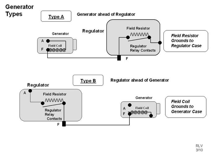
The notes in question are for a 650 Ford which would be a type B charging circuit.
Looking at the notes:
"1. Using volt meter momentarily jump the ARM and BAT terminals. Charge should be about 7.8. If not, then replace the regulator.
2. Jump the ARM and FLD terminals. If there is a charge, then replace the regulator. "
Let's apply some life experience to note taking and understand that notes are often quickly written and later confusing to read.
With that in mind lets interpret note as probably intended:
1:Using volt meter (CONNECTED ACROSS THE BATTERY) momentarily jump the ARM and BAT terminals. Charge should be about 7.8. If not, then replace the regulator. This bypasses the cutout section of the regulator and would make sense.
Note 2. Jump the ARM and FLD terminals. If there is a charge, then replace the regulator. " applies full field to a TYPE B SYSTEM and tests the regulator side of the regulator box.
If applied to MF35 (Type A) it should be GROUND THE FIELD TERMINAL
Attached diagram shows difference between Type A and Type B.
A generator system, if properly configured can operate either positive or negative ground

")