
The 3 pt lift on my friend's 600 stopped working last year, someone else resolved this by replacing the lift cover O rings, but he had to double the pressure side to get the lift back. Recently the lift stopped working again which is where I signed on. We removed the cover and it looked like the double O rings were not sealing. I found some dimensions for the OEM O ring, located a replacement, but no improvement so we moved on to troubleshooting the pump. We cranked the tractor with the lift cover off. I understand we should have 1500-2000 psi, oil flowed out of the gallery, but did not "shoot" out. What should I see? I pulled the pump off, I believe it is a NCA600F (piston type). The pistons/cylinders are smooth no obvious signs of wear, pistons move freely in their cylinders, springs appear to be uniform strength. Before we drop significant bucks into a pump, is there a way to better diagnose the pump condition? There is also a problem with water getting into the hydraulic system as the oil was milky. I drained and replaced the reservoir, but are there locations where water typically enters the system?
You are using an out of date browser. It may not display this or other websites correctly.
You should upgrade or use an alternative browser.
You should upgrade or use an alternative browser.
- Thread starter BobW
- Start date
Low volume (gallons per minute) pump and with zero restriction there is zero pressure. With it all assembled, install a gauge on the test port & measure pressure. Most water comes from every day/night, hot /cold condensation, with some entry at the draft control spring/plunger, if tractor exposed to rain.(quoted from post at 14:32:52 02/29/12) The 3 pt lift on my friend's 600 stopped working last year, someone else resolved this by replacing the lift cover O rings, but he had to double the pressure side to get the lift back. Recently the lift stopped working again which is where I signed on. We removed the cover and it looked like the double O rings were not sealing. I found some dimensions for the OEM O ring, located a replacement, but no improvement so we moved on to troubleshooting the pump. We cranked the tractor with the lift cover off. I understand we should have 1500-2000 psi, oil flowed out of the gallery, but did not "shoot" out. What should I see? I pulled the pump off, I believe it is a NCA600F (piston type). The pistons/cylinders are smooth no obvious signs of wear, pistons move freely in their cylinders, springs appear to be uniform strength. Before we drop significant bucks into a pump, is there a way to better diagnose the pump condition? There is also a problem with water getting into the hydraulic system as the oil was milky. I drained and replaced the reservoir, but are there locations where water typically enters the system?
Why not go to CNH and get the right piston O-ring and back up washer. They are not expensive. If you don't have a local CHN dealer try Messick's. That should seal up the piston/cylinder and stop any major leaks.
JMOR is right for testing the pressure. But its possible is that the pump has lost its prime.
You can loosen the bleeder plug on the front of the pump and run the tractor for while. Let the oil pump out all over the place. Then tighten the plug and see what happens. Or get serious, plumb an elbow into the bleeder hole, attach a ball valve and then convert to a hose barb. Attach a length of clear tubing and run the tubing back to the fill port for the hydraulic fluid. Close the valve and start the tractor. Slowly open the valve and you should see oil flowing through the tube. I there are bubbles, run the tractor for a bit and see if the bubbles stop. If yes, close the valve and check the hydraulic function. If all is well, button her up and celebrate. If the bubbles just keep going - post back, you have seal leak in the pump.
Hope that makes sense.
urt is speaking from experience. Good advice.(quoted from post at 21:53:20 02/29/12) Why not go to CNH and get the right piston O-ring and back up washer. They are not expensive. If you don't have a local CHN dealer try Messick's. That should seal up the piston/cylinder and stop any major leaks.
JMOR is right for testing the pressure. But its possible is that the pump has lost its prime.
You can loosen the bleeder plug on the front of the pump and run the tractor for while. Let the oil pump out all over the place. Then tighten the plug and see what happens. Or get serious, plumb an elbow into the bleeder hole, attach a ball valve and then convert to a hose barb. Attach a length of clear tubing and run the tubing back to the fill port for the hydraulic fluid. Close the valve and start the tractor. Slowly open the valve and you should see oil flowing through the tube. I there are bubbles, run the tractor for a bit and see if the bubbles stop. If yes, close the valve and check the hydraulic function. If all is well, button her up and celebrate. If the bubbles just keep going - post back, you have seal leak in the pump.
Hope that makes sense.
I put a kit in the pump since we had the parts on hand, blew out the pressure and return lines to make sure there were no obstructions, blew air through the cover to confirm the lift piston moved, put everything back together, confirmed pump operation and oil flow at the pump bleeder plug and prepared to celebrate. It was short lived as we still have zero movement of the lift arms.
The O ring I referred is between the lift cover and the chassis where the hydraulic oil enters and returns from the lift cover. I have rummaged through 2 lift cover gasket kits and neither has anything that appears to fit properly. I found the right OD, but too thin to extend above the recess and create a seal (which is why they used 2 on the last repair). There were a couple that are plenty thick, but the OD is larger than the recess so they distort. I found a detailed description at Alma Tractor & Equip and located some hydraulic suitable O rings this exact size. They appear to fit properly and we have oil flow at the accessory port on the lift cover when the accessory lever is "on". So I'm guessing we are sealed well enough that the lift should at least move with no implements attached. What do you think?
So if we have hydraulic pressure to the lift cover, where should I look next? I see we have a pressure relief valve in the cover and the piston/'valve assembly. Are there any other possibilities? Is it advisable to actually measure the pressure delivered to the lift cover? Where do I plumb the test gauge, into the accessory port?
Thanks.
So you are back to square one Bob. I've been there several times, fun isn't it. At least you know whats new and have gained a lot of knowledge. I pulled my top cover 4 times before I got everything right. Lots of work, but it was worth it.
So, you have flow at the test port on the 3X5 plate under the seat. That's good, but do you have pressure. Plumb a gauge into the test port and give it try. If you have pressure, I'm thinking a stuck unloader valve or bad linkage. The gauge should tell. No pressure we are back to chasing major leaks or pump prime.
Your comment about the o-rings between the top cover and center housing concerns me. Those two o-rings should be in the kit. How deep was the recess they fit in. Should only be about 1/16" deep? If its deeper something is wrong. A leak there could be your problem. If you pull your PTO Lever/Cover, run the tractor, you might be able to look in and see the leak. A good mirror and flashlight helps.
Hang in there you'll get it. Keep us posted, we are all learning as we go.
Kurt
(quoted from post at 13:27:36 03/12/12) I put a kit in the pump since we had the parts on hand, blew out the pressure and return lines to make sure there were no obstructions, blew air through the cover to confirm the lift piston moved, put everything back together, confirmed pump operation and oil flow at the pump bleeder plug and prepared to celebrate. It was short lived as we still have zero movement of the lift arms.
The O ring I referred is between the lift cover and the chassis where the hydraulic oil enters and returns from the lift cover. I have rummaged through 2 lift cover gasket kits and neither has anything that appears to fit properly. I found the right OD, but too thin to extend above the recess and create a seal (which is why they used 2 on the last repair). There were a couple that are plenty thick, but the OD is larger than the recess so they distort. I found a detailed description at Alma Tractor & Equip and located some hydraulic suitable O rings this exact size. They appear to fit properly and we have oil flow at the accessory port on the lift cover when the accessory lever is "on". So I'm guessing we are sealed well enough that the lift should at least move with no implements attached. What do you think?
So if we have hydraulic pressure to the lift cover, where should I look next? I see we have a pressure relief valve in the cover and the piston/'valve assembly. Are there any other possibilities? Is it advisable to actually measure the pressure delivered to the lift cover? Where do I plumb the test gauge, into the accessory port?
Thanks.
What does this mean? "....and we have oil flow at the accessory port on the lift cover when the accessory lever is "on". "Accessory lever is on" sounds like you have some kind of valve, maybe a Selec-trol-valve or the like? If you don't then the test port is #2 in far right image/photo. If not like this, then where are you talking about having flow?
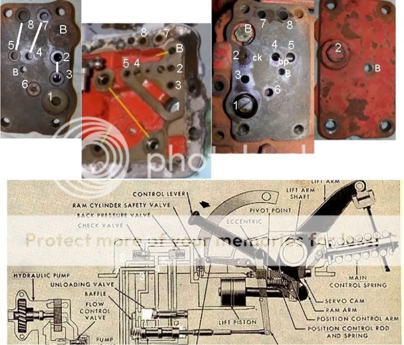
JMOR There is ~3x5" plate on the top of the lift cover that I understand is where a hydraulic accessory can be plumbed in. It has a 3/8" female NPT fitting with a plug in it. I think it is labeled 2 in your far right photo. There is a lever on the right side of the transmission housing that turns hydraulic flow on and off to this port. I removed the plug, put the lever in the "on" position and got a flow of hydraulic oil flowing from the port. Sorry, haven't quite figured out how to display a picture here so follow this link to the exploded parts diagram for Ford 600 hydraulic system: http://partstore.agriculture.newholland.com/us/AlmaTractorEquipmentInc/parts-search.html#epc::mr04-114ar04-114-57-39248 The lever is labeled 32, the plug is 19.
Kurt How much pressure should there be at this port? The recess is machined maybe a bit more than 1/16" does not appear boogered. The O ring called out in the link above is .487" ID x .103" thick. The o rings stick up a bit above the gasket surface so they should compress and seal when the top is bolted down. I looked at the operation of the lift linkage, nothing broken or detached and it appears to be moving the valve linkage in and out.
Kurt How much pressure should there be at this port? The recess is machined maybe a bit more than 1/16" does not appear boogered. The O ring called out in the link above is .487" ID x .103" thick. The o rings stick up a bit above the gasket surface so they should compress and seal when the top is bolted down. I looked at the operation of the lift linkage, nothing broken or detached and it appears to be moving the valve linkage in and out.
hat is not an ON/OFF lever for the test port....that is your POSITION/ DRAFT control lever. The pressure you see at that port depends entirely on the load being lifted by the drawbar lift arms.(quoted from post at 22:13:39 03/12/12) JMOR There is ~3x5" plate on the top of the lift cover that I understand is where a hydraulic accessory can be plumbed in. It has a 3/8" female NPT fitting with a plug in it. I think it is labeled 2 in your far right photo. There is a lever on the right side of the transmission housing that turns hydraulic flow on and off to this port. I removed the plug, put the lever in the "on" position and got a flow of hydraulic oil flowing from the port. Sorry, haven't quite figured out how to display a picture here so follow this link to the exploded parts diagram for Ford 600 hydraulic system: http://partstore.agriculture.newholland.com/us/AlmaTractorEquipmentInc/parts-search.html#epc::mr04-114ar04-114-57-39248 The lever is labeled 32, the plug is 19.
Kurt How much pressure should there be at this port? The recess is machined maybe a bit more than 1/16" does not appear boogered. The O ring called out in the link above is .487" ID x .103" thick. The o rings stick up a bit above the gasket surface so they should compress and seal when the top is bolted down. I looked at the operation of the lift linkage, nothing broken or detached and it appears to be moving the valve linkage in and out.
That description of the top cover to center section housing or-ring sounds normal to me. As long as the o-ring stand proud of the gasket all is well.
JMOR answered your question on pressure a the test port.
If you had the pump apart and it had 6 pistons, you have a piston pump. Should look like this.

Do you have the pump and top cover off the tractor? Or is every thing buttoned up?
JMOR answered your question on pressure a the test port.
If you had the pump apart and it had 6 pistons, you have a piston pump. Should look like this.
Do you have the pump and top cover off the tractor? Or is every thing buttoned up?
Yes we have a piston pump. Everything is assembled at the moment.
After some reading I now understand the use/purpose of the Draft Control lever, although I'm not sure how it actually works. So is the test port simply an access point for measuring hydraulic pressure?
When the DC lever is horizontal no oil flows out of the test port, when the lever is vertical it does. Is that working correctly?
I see JMOR's remark about needing the system to be closed to build hydraulic pressure, but not about the working pressure of the system. I will need to purchase a gauge and need an idea of what capacity.
"When the DC lever is horizontal no oil flows out of the test port, when the lever is vertical it does. Is that working correctly?" No, fluid pressure will be present at that port anytime the lift is being raised or when it is in up position, holding a load. 1950 to 2050 PSI.(quoted from post at 12:43:42 03/13/12) Yes we have a piston pump. Everything is assembled at the moment.
After some reading I now understand the use/purpose of the Draft Control lever, although I'm not sure how it actually works. So is the test port simply an access point for measuring hydraulic pressure?
When the DC lever is horizontal no oil flows out of the test port, when the lever is vertical it does. Is that working correctly?
I see JMOR's remark about needing the system to be closed to build hydraulic pressure, but not about the working pressure of the system. I will need to purchase a gauge and need an idea of what capacity.
I got to thinking after I posted early this morning, and that's a dangerous thing at my age. I may not fully understand what you have done so far. This is what I think the situation is.
Symptom: With the tractor running, moving the Touch Control Arm up and down does not result in any motion of the lift arm.
What you have done.
1. Taken the piston pump apart and verified that the piston and spring are in good condition.
2. Removed the top cover and replaced the main piston O-ring and back up washer. Installed new top cover O-rings and new top cover gasket.
Symptom is still the same.
From here I would go back to basics first. Hydraulic systems are very simple, its the valving that's complicated on the 600/800 series tractor. So lets check the basics first before you take anything else apart.
There are three basic parts of the hydraulic system. 1. Pump, 2. Valves, 3 Slave cylinder (piston). The pump and cylinder is what I would check first.
1. Testing the pressure at the test port is good starting point. You can also test the pressure at the bleeder port of the pump. Pressure should be about 2000 psi.
2. Check for pump prime. From the pump bleeder port, convert to a barbed fitting and run clear plastic tubing back to the hydraulic oil fill port. Start the tractor and watch the oil run through the tube. If no oil is moving, or if there are bubbles moving along the tubing, you have a pump problem. Stop the tractor and replace the plug.
3. Check the main cylinder for leaks, Remove the PTO lever cover (round cover under the seat on the left side). Put some weight on the lift arms. Start the tractor and take a look inside. You can see the back side of the cylinder. If oil is flowing there you have a leak.
Might be worth a try?
Yep! Parts get expensive in a hurry. Try the simple and cheap stuff first. You can usually get a pressure gauge at Tractor Supply for about $30. Still might need some fittings.
My experience says the usual problems on the hundred series hydraulic system are (in order of likelihood)
1. O-Ring/Backup washer failure on the slave cylinder (main top cover cylinder)
2. Leaking shaft seal on the hydraulic wobble shaft in the piston pump. (Can't get pump to hold prime)
3. Bad/Stuck unloader valve O-ring (erratic lift)
4. Worn control valve (usually results in hiccups or bobbing)
5. Other blown O-rings or bad gaskets (could be any of them)
6. Crap in the check valves or back pressure valve
7. Worn check valve springs and balls in the piston pump.
8. Bad Safety or Relief valve (rarely a problem)
9. Ruptured / corroded tubes in the center section or transmission. (A leak in the transmission pressure tube results in a gain of oil in transmission - this is a common problem in these old tractors, but the hydraulics may still work if it not too bad.
That assumes all the linkage is in good condition and in adjustment.
Good Luck!
Kurt
Ran the hose from the pump to the fill port, the oil is a bit milky but no evidence of air bubbles. Flow pulses, I am guessing as each piston is engaged? Installed a 3000 psi gauge in the test port on the lift cover, cranked up, put the draft lever in down position, needle did not move off the stop. Tried all combinations of draft lever and lift control, no pressure indicated. Backed the gauge out of the test port to make sure we had oil coming to it, there was. Let it bleed out a bit looking for air bubbles, saw none. Guess this indicates an internal leak/bypass so we don't build any pressure?
Bypass" is likely key word. Sounds more & more as though your unloader valve is stuck in the position where it is allowing all flow to be directed through the low pressure (~40psi) back pressure valve & return to the sump. You seem fairly intent on seeing that pump is actually capable of producing pressure. This can be accomplished by blocking flow ahead of the unloader & back pressure valves. This is done by installing the 3X5 plate with the left side (in my earlier pictures it is at bottom of picture) positioned over the right side (top of my picture) of the top cover (use piece of gasket material or tablet backing card board between the two). What this does is block #7 (the feed from the pump). Now, when you start engine/pump, the only place for flow to go is to the overpressure safety relief valve in belly of hyd compartment. It should relieve at 1950-2050 PSI & you may hear it buzzing or squealing. You will need to connect your gauge at the pump (same place you connected hose to observe for bubbles). If pressure good here with this set up, you can have some degree of confidence that it is the unloader valve. If still no pressure, we go elsewhere in our investigation.(quoted from post at 17:39:25 03/14/12) Ran the hose from the pump to the fill port, the oil is a bit milky but no evidence of air bubbles. Flow pulses, I am guessing as each piston is engaged? Installed a 3000 psi gauge in the test port on the lift cover, cranked up, put the draft lever in down position, needle did not move off the stop. Tried all combinations of draft lever and lift control, no pressure indicated. Backed the gauge out of the test port to make sure we had oil coming to it, there was. Let it bleed out a bit looking for air bubbles, saw none. Guess this indicates an internal leak/bypass so we don't build any pressure?
Despite a blow out of the cardboard gasket we built 1000 psi pressure so I think we can check off the pump and substitute O rings and move on. We replaced all the O rings beneath the plate for good measure.
I looked inside the transmission, we have some water there, but rust on the mating surfaces of the plug suggest water enters there as this tractor sits outside. I noticed some froth and that the oil churns when the engine is running. Is there an oil pump in the transmission?
It sounds like we move on to the unloader valve which looks like it is part of the valve/cylinder assembly attached to the lift cover?
o transmission pump, just oil being stirred by turning gears...push in clutch & it should stop. Hydraulic tubes do run through transmission connecting pump manifold to hydraulic area & if those rust thru, then hyd fluid will be transferred from hyd sump to the transmission. Yes, unloader valve is within the lift cylinder/valve assembly below the top cover.(quoted from post at 12:11:16 03/15/12) Despite a blow out of the cardboard gasket we built 1000 psi pressure so I think we can check off the pump and substitute O rings and move on. We replaced all the O rings beneath the plate for good measure.
I looked inside the transmission, we have some water there, but rust on the mating surfaces of the plug suggest water enters there as this tractor sits outside. I noticed some froth and that the oil churns when the engine is running. Is there an oil pump in the transmission?
It sounds like we move on to the unloader valve which looks like it is part of the valve/cylinder assembly attached to the lift cover?
A couple of pictures - location of the unloader valve.


Post back when you are ready, I can help you get the plug out. The valve body can be pushed out thought the other end with a thin rod. It has an O-ring on it that need to be replaced. Make sure you get the right O-ring, its an odd size. Messick's has them.
Kurt
Post back when you are ready, I can help you get the plug out. The valve body can be pushed out thought the other end with a thin rod. It has an O-ring on it that need to be replaced. Make sure you get the right O-ring, its an odd size. Messick's has them.
Kurt
I chased lift problem on an 801 for a couple of months. Couldn't build more than 400 psi of pressure. Totally rebuilt the pump including the wobble plate at the rear as well as everything else. Cover on and off several times. I listened to everyone tell me it wasn't the relief valve. At the end of my rope bought one and installed it. A few bucks and 30 min work. That was the problem, works like a champ for 3 years now. Moral: Rarely doesn't mean never
Did you replace the safety valve or the relief valve. The safety valve is the one under the 3X5 plate on the top of the top cover. The relief valve installs from the bottom of the center housing.
Either one can fail and cause a leak, but they rarely fail. They are not too expensive to replace and easy to get to.
I'm glad to hear you got it fixed. These systems work great, but can be a bear to diagnose.
Kurt
Either one can fail and cause a leak, but they rarely fail. They are not too expensive to replace and easy to get to.
I'm glad to hear you got it fixed. These systems work great, but can be a bear to diagnose.
Kurt
We have to the cover off and are ready to remove the unloader valve.
I notice the linkage is fairly loose and could be tightened with a castle nut (linkage in photo) , how much play is too much? There is also a pin at about the midpoint of the linkage arm with nothing attached. I don't see anything explanation of what this is in the manual.
Thanks,
Bob
 [/img]
I notice the linkage is fairly loose and could be tightened with a castle nut (linkage in photo) , how much play is too much? There is also a pin at about the midpoint of the linkage arm with nothing attached. I don't see anything explanation of what this is in the manual.
Thanks,
Bob
Yep, the linkage on mine was sloppy too, don't get too concerned about it. Do you have a copy of IT Ford Shop Manual, no. F0-20? It has a description of how to adjust the linkage. If not, get one before you go twisting on those nuts. Zane Sherman also sell a nice booklet for doing the adjustments. The good news on the hundred series is that they don't go out of adjustment easily. Of course you don't know who else has been in there monkeying around.
Don't worry about the pin, its just a stop for the linkage.
From what I can see in your picture, your linkage looks OK. How does the Cam Follower Pin look?
Have you started to check out the unloader valve yet?
Kurt
Don't worry about the pin, its just a stop for the linkage.
From what I can see in your picture, your linkage looks OK. How does the Cam Follower Pin look?
Have you started to check out the unloader valve yet?
Kurt
(quoted from post at 15:42:30 03/19/12) Yep, the linkage on mine was sloppy too, don't get too concerned about it. Do you have a copy of IT Ford Shop Manual, no. F0-20? It has a description of how to adjust the linkage. If not, get one before you go twisting on those nuts. Zane Sherman also sell a nice booklet for doing the adjustments. The good news on the hundred series is that they don't go out of adjustment easily. Of course you don't know who else has been in there monkeying around.
Don't worry about the pin, its just a stop for the linkage.
From what I can see in your picture, your linkage looks OK. How does the Cam Follower Pin look?
Have you started to check out the unloader valve yet?
Kurt
Pin looks O.K. How do you remove unloader valve, which direction?

I am not recognizing anything as being "broken" that would cause a complete failure of the hydraulics. Do you suggest replacing snap ring and seeing what that does? Anything else we should do while we have everything apart? I understand the safety valve was replaced ~5 yrs ago.


here was the spool in the bushing, toward the rear of tractor or toward the front of tractor?(quoted from post at 12:28:42 03/19/12) I was driving out the valve and bushing together, hard to say
I am fuzzy on the hydraulic flow and what valve does what. If there is pressure to the lift cover and we move the control lever, the control valve directs oil into the lift cylinder and the lift raises? Since this does not happen even with no implement attached, seems like either we are failing to move the control valve properly (linkage) of the oil is not reaching the control valve. Are either the unloading valve or the control valve between the control valve and the oil entering the lift cover?
do not know a dimension for the amount of unloader spool movement, but I can help you figure it out. Look at he picture I posted early on here. See the white number "5". That passage going down to the unloader valve is accompanied by another passage just to the right. The spool is shown to right in this picture (in a position to block a common connection of these two passages)....this is shown in position in the position to "LIFT". If spool is moved far enough to left to allow the small diameter of spool to provide a path connecting the "5" passage & passage parallel to it together, then it would be in "hold" or "lower" (same for unloader valve). Between those two positions would be your answer as to 'how much does spool move'.(quoted from post at 12:42:02 03/19/12) I did not notice there was any movement of the spool when I started. I was unclear which way it came so I initially tapped on it lightly from both sides, Seems like I would have noticed movement. How much is the travel?
The amount of spool travel is not important.
the check the piston we blew air into the gallery where the oil enters the lift cover which I believe is the forward hole.
The spool and snap ring look to be in good condition so let's reinsert and check clearance/freedom of movement. Any experience/tips on how to compress the snap ring so it will slide into the bushing?
Bob's words: "I am fuzzy on the hydraulic flow and what valve does what. If there is pressure to the lift cover and we move the control lever, the control valve directs oil into the lift cylinder and the lift raises? Since this does not happen even with no implement attached, seems like either we are failing to move the control valve properly (linkage) of the oil is not reaching the control valve. Are either the unloading valve or the control valve between the control valve and the oil entering the lift cover?"
My response: No, the control valve does NOT direct oil into the lift cylinder.
To initiate "LIFT", the linkage moves the control valve toward the front of tractor, which allows smaller left portion of its spool to connect the passages leading to both the left & right sides of the steel-ringed part of the unloader valve. This puts equal pressure on both sides of the steel-ringed 'piston' & since the area of the left side is larger than the area of the right side, the force moves it to the right. This positions the rear smaller diameter of the unloader spool such the it blocks the "5" passage from connecting to the parallel passage to the right of "5". This blocks the free flow from the backpressure valve to dump into the sump. Once the free flow is blocked, then the pressure rises & has no other place to go other than through the check valve & into the lift cylinder. You should be able to follow all this in the diagram which I posted earlier.
In a nut-shell, the unloader valve is closer to directing the flow to lift ram cyl that the control valve. The control valve ultimately controls this, but in a rather indirect fashion which I just described.
At least the cam follower pin is OK. The unloader valve comes out from the opposite end of the cylinder from that shown on your picture. You should see a plate with 3 bolts there. Remove the bolts slowly, there is a spring under it that works with the control valve. Next to the spring you will see the plug JMOR talked about. Its about 1-1/8" diameter with a threaded hole. I think JMOR is right about it being tapped 1/2-20 - that's a fine thread. You will need to get a bolt that fits it, about 1-1/2 to 2" long. Also get a fist full of 1/2" flat washers. Beg, borrow, or acquire a piece of steel plate and drill a 1/2" hole in it. Put the bolt thought the hole in the plate and then into the plug. Put some washers under the plate to support it. Then tighten the bolt. It will pull the plug out. You'll have to repeat that several times adding washers each time.
Once the plug is out you can push the unloader valve out from the other end with a small roll. If its stuck, you found your problem. It should move easily. Clean everything up and put on new O-ring. Don't use abrasives. Oil it up and reinstall. You can tap in the plug with a hammer, just be gentle.
Make sure you used the correct O-ring on the unloader valve. Don't guess. I get mine from CHN
Keep us posted,
Kurt
Pin in Geo March's NAA.but very much like hundred series:(quoted from post at 17:48:39 03/19/12) It might be wise to clearly ID the cam follower pin.
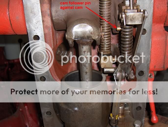
The pin looks good.
We reassembled the valves and piston, put the cover back on and this time a celebration was in order. Although we replaced a number of O rings, none were in bad shape shape so I think your diagnosis of something going on with the unloader valve was the right call, probably stuck "open". If this recurs we'll replace the innards.
JMOR and Kurt thank you both for the help and patience in dealing with a beginner.
Bob
ou are welcome. Glad you got it working!(quoted from post at 16:39:56 03/20/12) The pin looks good.
We reassembled the valves and piston, put the cover back on and this time a celebration was in order. Although we replaced a number of O rings, none were in bad shape shape so I think your diagnosis of something going on with the unloader valve was the right call, probably stuck "open". If this recurs we'll replace the innards.
JMOR and Kurt thank you both for the help and patience in dealing with a beginner.
Bob
Wow! I just read this entire thread for about the 10th time. I'm having a similar problem with my 600 series tractor and I'm more confused than ever. My hydraulic lift works sporadically. It stopped working for a while and I remove the #2 cap screw on the top cover and filled the passage with oil. This seemed to help and it worked for a while then quit again. When I got the machine it was fairly hammered and I noticed that the lift lever and housing was bent like it was run into something and pushed back about an inch. I bought a new (used) housing and arm and replaced and again it worked for a while. Now it's not working. Any thoughts? Should I start by replacing the hydraulic cover gaskets? Or throw myself in front of a bus? Help!
Don't step in front of the bus yet. Lets do some troubleshooting.
Answer a few questions to get us started.
1. What tractor do you have?
2. What are the symptoms?
3. By the No. 2 hole do you mean the hydraulic sump fill port - Big plug under the seat or the the pipe plug on the 3"X5" accessory plate in front of the center housing?
4. Did you pull the top cover to change the touch control lever and frame?
5 It sound to me like you have erratic operation. Some times it works and some times it does not. When its working, is it completely normal or does is sorta work?
Typical problems with hundred series hydraulics involve the following. If you decide to pull the top cover, I would service 1-4. Do number 5 only if you have to.
1. Leak in main cylinder/piston O-ring. Replace the O-ring and backup washer. I would use CNH parts here
2. Worn or broken cam follower pin. Replace it if there is any wear at all.
3. Gummed up unloader valve. Clean and replace the O-ring. Again I would use the CNH O-ring
4. Dirty or water contaminated hydraulic fluid - Change it
5. Loss of prime - Rebuild the hydraulic pump.
But before you do anything - lets diagnose it . Don't pull that top cover!. There are things we can do to pin down the problem
Here is a picture of the underside of a hundred series top cover. It may help a bit.

Kurt,Answers to your questions;
1 1956 Ford 640 s/n 640 95247
2 Symptoms are sporadic functioning of the lift on the hydraulic arms for TPH.
3 Yes, I changed the oil and filled through the big plug but have been priming through the smaller pipe plug on the 3x5 accessory plate (#2). This sometimes gets the arms to rise and they work for a couple of days but then they stop functioning.
4 I haven't pulled the top cover yet as I was hoping that I might not have to. 5 I didn't work at all when I got the tractor last spring. I notice that the touch control lever was missing the friction disc. When I disassembled it I found the housing that the shaft runs in was bent back towards the axel about a inch or maybe a little more. I replaced the damaged parts and could usually get the system to lift by adding oil into the #2 pipe plug. Recently this isn't doing any good. I have noticed that the lever for implement position control and constant draft control can be turned so that its pointing straight up as well. sometimes causes the pump to change its out put. But not too often. I'm hoping that maybe all it needs is fresh o rings under the accessory plate. I've had this off a couple of times the rings aren't broken but look kind of hard. Is this at all clear? Or have I confused you as well?
Cheers
Mike
Thanks for the info.
From what you have said, I think you are loosing prime at the pump.
Does you pump look like this?
If yes, you can prime it my loosening the pipe plug on the top of the pump with the engine at very slow idle. Have a catch pan under it and lots of rags. Loosen the plug just enough to get flow. Let it run until all the bubbles stop. Tighten the plug and try the hydraulics without stopping the tractor. If the hydraulics work OK, you have an intake leak on you pump.
Alternately, you can plumb out of the pipe plug into an elbow and ball valve, the adapt to some clear vinyl tubing. Route the tubing back to the fill hole. Start the tractor and crack the valve. You should see oil going through the vinyl tubing. If you see bubbles, you have a pump intake leak. This method sure is neater, but costs more. You can run the tractor this way for a while until you get the leak fixed. Just close the valve to use the hydraulics.
I would start with this before you consider removing the top cover. Also, the o-rings for the 3X5 accessory plate come with the Tisco top cover gasket set. Not too expensive. This site sells it. Might be worth the investment. For me, I would buy two sets. I always keep one on the shelf just in case.
was thinking the same thing as I read his "priming' method........simple fluke, I guess, because sure not going to prime from that point!(quoted from post at 15:53:20 11/26/12) I got to thinking some more. Putting oil in the 3X5 accessory plate is adding oil to the pressure side of the pump. Doesn't make sense that that would start things working. I would still try priming the pump first. Its cheap and easy.
That is one of the puzzling bits in this whole deal. The first couple of times I pulled that top pipe plug I got a pretty good spray of oil. thats when the arms started lifting pretty good. Now they don't lift at all and when I pull the plug with the engine running, nothing which makes no sense to me. Also priming through the hole does nothing. Would that be the o rings leaking maybe?
If you pull that accessory plate plug with the tractor running you should be sprayed. And that is putting things mildly. If you have nothing there now, your pump is not pumping. It could be air bound, or something broke in the pump. I guess it also possible that the suction side is plugged, but somehow I doubt that. Try to prime it. If you get nothing out the pump plug, I'd pull the pump and check it out. Possible stripped gear or broken wobble shaft.
BTW, You do have a round piston pump? Right?
BTW, You do have a round piston pump? Right?
o get oil out that test port, from the pump, the unloader valve has to be in its lift position & the pressure must be enough to overcome the check valve (~115psi). The other way to get oil out that port is to have the lift arms going down (pushing lift piston back into its bore), thus dumping that cup of oil out the test port.(quoted from post at 17:17:32 11/26/12) That is one of the puzzling bits in this whole deal. The first couple of times I pulled that top pipe plug I got a pretty good spray of oil. thats when the arms started lifting pretty good. Now they don't lift at all and when I pull the plug with the engine running, nothing which makes no sense to me. Also priming through the hole does nothing. Would that be the o rings leaking maybe?
Think of it this way. Hydraulic systems consist of 3 main systems. A pump, a valve, and a cylinder/piston. On the hundred series tractor, the pump is driven off the flywheel and is straight forward, the cylinder/piston is very simple, just a piston in a cylinder. The hard part to understand is the valve. Its actually four valves working together. A control valve, an unloader valve, a check valve and a back pressure valve.
Problems with the cylinder/piston is usually a leak that lets the load drop with the tractor off. That's not your problem
The valves are complicated - JMOR continues to education me on these.
For now I would concentrate on making sure the pump is working. The bleeder is located on the top of the pump toward the front of the tractor.

It takes an Allen wrench to remove. To bleed just back it out until you have oil flow. If no flow, then you have a problem in pump part of the system. If you get bubbles, then you have a suction side leak. If you get all oil, then we can move on the valves.
Problems with the cylinder/piston is usually a leak that lets the load drop with the tractor off. That's not your problem
The valves are complicated - JMOR continues to education me on these.
For now I would concentrate on making sure the pump is working. The bleeder is located on the top of the pump toward the front of the tractor.
It takes an Allen wrench to remove. To bleed just back it out until you have oil flow. If no flow, then you have a problem in pump part of the system. If you get bubbles, then you have a suction side leak. If you get all oil, then we can move on the valves.
ressure test: see my post at about march 14 or 15 in this thread(quoted from post at 18:58:01 11/26/12) Yep, it's a pump like the one in the picture. It's got me baffled. Whats the correct way to prime it? And what should I use? ATF, hydraulic? Is there any way to check pressure at the pump? If it was bad wouldn't it have not worked at all? So many questions!
I forgot to say. The proper hydraulic fluid is Universal Tractor Fluid (UTF). Check for Ford specification MC134C or D. Its available at most farm stores like Farm and Fleet or Tractor Supply. Also available at Walmart and many rural auto parts stores like NAPA.
Don't use gear oil 80W90 or Automatic Transmission Fluid.
Don't use gear oil 80W90 or Automatic Transmission Fluid.
It's hard to tell because it's dark and cold up here in the frozen northland but I put my finger over the hole after I filled it and I think I could sort of feel little pulsing but not a lot. I ran the engine revs up and it didn't make any difference. What kind of job is it to pull that pump?
I've never heard of a pump doing this unless the gear wasn't driving the wobble shaft. Maybe someone else will have an opinion.
Pulling the pump is easy. Two bolts into the block and 3 nuts on the studs holding the manifold in place on the bottom.
There is a gasket between the pump and block that will need to be replaced, but you can probably leave that until later, a little engine oil coming out here is a minor problem. There are two flat o-rings on the bottom of the pump where it attached to the manifold. You can probably clean these up an re-use them.
If you are going to pull the pump, Order the gasket and o-rings from CNH. Use www.external_link to order on-line. They are not big buck items, but shipping is horrendous. I don't like the Tisco replacement parts here.
If you decide to rebuild the pump, make sure you are up to it. You'll need a shop press and some background in working with bearings and seals. If this scares you, find a dealer to do it for you. Cost is about $150-200 for parts alone. Rebuilt and used pumps often surface on Ebay, but are pricey. If the gear is toast, you'll need to find a used one.
If you decide to do the rebuild yourself post back, we can help. I could do one in a afternoon with several beer breaks. Its not even a six-pack job.
Parts required for a rebuild are a pump re-build kit, main bearing cup and cone, wobble shaft, and needle bearing. This site had them. That is in addition to the gasket and flat o-rings from CNH.
When I got my first tractor, an 8N, I understood everything except the hydraulics. Took me a long time to get the hang of it. When I got my 660 things just got more complicated. That said, the hydraulics on my 660 are light years ahead of an 8N.
BTW, if you pull the top cover, get Zane Sherman's kit on adjusting the hundred series hydraulics. Well worth the money.
BTW, if you pull the top cover, get Zane Sherman's kit on adjusting the hundred series hydraulics. Well worth the money.
That's good news. I guess? At least we are narrowing things down.
I see three possibilities
1. Something is wrong with pistons and valves inside the pump.
2. The wobble shaft seal is blown - allowing air to be pumped through the pump. For it to be this bad, the seal must be gonzo.
3. Oil is not getting to the suction side of the pump.
I doubt number three. But, you could loosen the bolts at the bottom of the manifold. Where it goes into the transmission. If oil flows out, its open. Tighten it up and hope it seals. Or drain the oil, take the manifold off. There are two tubes running back through the transmission and into the sump. Run a rod through both of them and make sure they are open (A rifle cleaning rod works well for this - put a patch on and clean them out). Also check the two passages inside the manifold are open.
Number 1 and 2 involve pulling the pump. Are you up to a pump rebuild?
hread is so long that I don't remember & am not going to re-read all the pages, BUT, has anyone mentioned applying compressed air to the fill hole to see if it will pick up/prime?(quoted from post at 07:19:47 11/27/12) That's good news. I guess? At least we are narrowing things down.
I see three possibilities
1. Something is wrong with pistons and valves inside the pump.
2. The wobble shaft seal is blown - allowing air to be pumped through the pump. For it to be this bad, the seal must be gonzo.
3. Oil is not getting to the suction side of the pump.
I doubt number three. But, you could loosen the bolts at the bottom of the manifold. Where it goes into the transmission. If oil flows out, its open. Tighten it up and hope it seals. Or drain the oil, take the manifold off. There are two tubes running back through the transmission and into the sump. Run a rod through both of them and make sure they are open (A rifle cleaning rod works well for this - put a patch on and clean them out). Also check the two passages inside the manifold are open.
Number 1 and 2 involve pulling the pump. Are you up to a pump rebuild?
There are 18 springs in the pump. 6 on the pistons, and 12 on the check valves. Any of them can fail. So its possible. Usually its just one that breaks, the efficiency of pump falls and you might get the jitters. But one piston spring could take out another and then another until you get nothing. The check valve springs are quite small - usually do little damage when they wear out.
A pump rebuild kit will include the springs. This site has the kit. Not too expensive, not too difficult to put in. The kit is about $40 plus shipping.
Its the wobble shaft seal this is more difficult to replace. Don't go there unless you have to.
Shoot me an email and I'll send some documentation on the pump. Well worth a read. My email is open on the Modern side of the forum.


Wow,
Nice, that shows the deal. I can't figure out where your email is but you can reach me @ [email protected].
Thanks
Mike
Nice, that shows the deal. I can't figure out where your email is but you can reach me @ [email protected].
Thanks
Mike
Similar threads
- Replies
- 1
- Views
- 104
- Replies
- 3
- Views
- 201
We sell tractor parts! We have the parts you need to repair your tractor - the right parts. Our low prices and years of research make us your best choice when you need parts. Shop Online Today.
Copyright © 1997-2024 Yesterday's Tractor Co.
All Rights Reserved. Reproduction of any part of this website, including design and content, without written permission is strictly prohibited. Trade Marks and Trade Names contained and used in this Website are those of others, and are used in this Website in a descriptive sense to refer to the products of others. Use of this Web site constitutes acceptance of our User Agreement and Privacy Policy TRADEMARK DISCLAIMER: Tradenames and Trademarks referred to within Yesterday's Tractor Co. products and within the Yesterday's Tractor Co. websites are the property of their respective trademark holders. None of these trademark holders are affiliated with Yesterday's Tractor Co., our products, or our website nor are we sponsored by them. John Deere and its logos are the registered trademarks of the John Deere Corporation. Agco, Agco Allis, White, Massey Ferguson and their logos are the registered trademarks of AGCO Corporation. Case, Case-IH, Farmall, International Harvester, New Holland and their logos are registered trademarks of CNH Global N.V.
Yesterday's Tractors - Antique Tractor Headquarters
Website Accessibility Policy