TO-30 Wiring question

JasonKS

Member
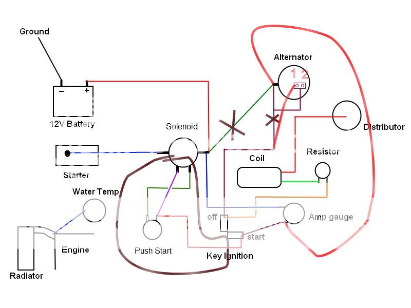
Here's the wiring diagram, although my original problem is fixed (bad ground cable), thanks to the help from people on this forum. The tractor runs fine now, but I want to post this wiring diagram because I am not sure the battery is charging correctly.

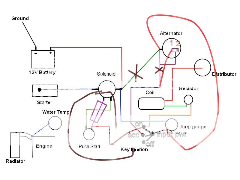
A couple of explanatory notes regarding the diagram. I only have two gauges on the tractor: 1. Amp gauge, 2. Water temperature gauge. There is no oil pressure gauge, nor does there appear to be a cut out in the dash for one. Per the manual, the water temp gauge should be an oil pressure gauge. The amp gauge either doesn't work or the alternator isn't working. The wiring from the alternator looks a little odd. There is the single post, but there is also a two-prong clip, which has a single wire coming out and that is spliced into the wiring going from the post to the "off" position of the key ignition.

Let me know if anything here looks awry. I am also not sure if the component I labeled "resistor" is really a resistor or something else. Thanks for your help.

http://img.photobucket.com/albums/v635/rubinsteinak/51TO-30Wiring.jpg
 
It looks like alt. isn't right the wire on the post
to the solenoid is good but the wire to key needs to
be on prong 1 then prong 2 is a short one back to
the post.
 
I just found this article in the "Articles" section of this site.

http://www.ytmag.com/articles/artint195.htm

You are correct. Prong 2 should be going to the BATT terminal on the alternator. However, if I'm reading this right, Prong 1 should be going to the "start" position on the key ignition, not the "off" position. Is this correct?

Right now, the wiring has been electrical taped, giving the impression that the wires coming out of the prongs are spliced into the other wire from the post to the Off position. I will unwrap this wiring this weekend and figure out what's going on. Thanks for your help.
 
Cut the "X" marked wires & replace with bold red wires. If a "one-wire' alt, then you may need no connection to alt #1.....so you should try it first without it. You do not, in any case want the wire with the small "X" connected(it probably isn't connected like that anyway or else the power to coil would always be present & Ign sw wouldn't turn it off) . As for the starting area encircled, it does not look right to me, but if it starts????????

fergy_wire.jpg
 
Thanks for the response. I think you're probably right about the Prong 1/2 connections. I will take the tape off to make sure, but I think Prong 2 goes to the BATT connection on the alternator, and I think Prong 1 goes to the OFF position on the ignition, as shown by the short bold red line you added.

As for your other bold red line from the BATT connection on the alternator to the Amp gauge, does your tractor have a wire going from the alternator to a dash-mounted amp gauge? It makes sense, though, because the gauge would then directly read the amps coming out of the alternator. The way it's hooked up now, would that prevent the alternator from charging the battery?

I'd be interested to hear how others with push-start and starter solenoid have theirs wired up. This is how it was wired when I got the tractor, and it does start just fine. What I'm not sure about regarding this part of the wiring is how the push start button and the key ignition work together. When the key is turned into the Start position, is that allowing current to flow from the battery, through the amp gauge, through the wire connecting the Start position to the push-start switch, which when pushed sends the current to the solenoid, which opens the pathway for the current to travel from the battery to the starter?
 
(quoted from post at 15:23:25 07/20/12) Thanks for the response. I think you're probably right about the Prong 1/2 connections. I will take the tape off to make sure, but I think Prong 2 goes to the BATT connection on the alternator, and I think Prong 1 goes to the OFF position on the ignition, as shown by the short bold red line you added.

As for your other bold red line from the BATT connection on the alternator to the Amp gauge, does your tractor have a wire going from the alternator to a dash-mounted amp gauge? It makes sense, though, because the gauge would then directly read the amps coming out of the alternator. The way it's hooked up now, would that prevent the alternator from charging the battery?

I'd be interested to hear how others with push-start and starter solenoid have theirs wired up. This is how it was wired when I got the tractor, and it does start just fine. What I'm not sure about regarding this part of the wiring is how the push start button and the key ignition work together. When the key is turned into the Start position, is that allowing current to flow from the battery, through the amp gauge, through the wire connecting the Start position to the push-start switch, which when pushed sends the current to the solenoid, which opens the pathway for the current to travel from the battery to the starter?
he alternator output current as on your original diagram would still go into charging the battery, but it does not pass thru the ammeter, so you have no meter indication that it is charging. As is, your ammeter reads ONLY load/drain current, not charging current, where my long red wire corrects that such that ammeter reads EVERYTHING , both into and out of battery. Even though you have your ign sw marked off & start, it appears to be a simple 2 pole on/off switch (off & run), with no 3rd position for start. If that is the case, all that is happening is that key must be on inorder for push to start switch to receive power, which when pushed then powers up the solenoid.
 
Even though you have your ign sw marked off & start, it appears to be a simple 2 pole on/off switch (off & run), with no 3rd position for start. If that is the case, all that is happening is that key must be on inorder for push to start switch to receive power, which when pushed then powers up the solenoid.

The ignition switch has three posts in the back. Only two have anything hooked to them. Presumably the positions are Off, On, Start, where "on" turns on the lights (if they were wired up). Does the current flow as I described in my previous post?
 
(quoted from post at 17:15:24 07/20/12)
Even though you have your ign sw marked off & start, it appears to be a simple 2 pole on/off switch (off & run), with no 3rd position for start. If that is the case, all that is happening is that key must be on inorder for push to start switch to receive power, which when pushed then powers up the solenoid.

The ignition switch has three posts in the back. Only two have anything hooked to them. Presumably the positions are Off, On, Start, where "on" turns on the lights (if they were wired up). Does the current flow as I described in my previous post?
s the Start position a spring loaded/must hold in Start position? but will rest in either off or run?
 
is the Start position a spring loaded/must hold in Start position? but will rest in either off or run?

No. You just turn the key into the start position, push the button and pull the choke, she starts, and I let off the push button and let the choke back in. There is no spring loading in the key ignition.

Also, sorry for such a dumb question and I don't want to change the subject, but why does the coil not need to be hooked to the battery? Where does it get its "juice"? I understand what the coil does, but not how it starts doing it, if that makes sense.
 
(quoted from post at 17:46:00 07/20/12)
is the Start position a spring loaded/must hold in Start position? but will rest in either off or run?

No. You just turn the key into the start position, push the button and pull the choke, she starts, and I let off the push button and let the choke back in. There is no spring loading in the key ignition.

Also, sorry for such a dumb question and I don't want to change the subject, but why does the coil not need to be hooked to the battery? Where does it get its "juice"? I understand what the coil does, but not how it starts doing it, if that makes sense.
es, the current flow is pretty much as you described. The ign switch is most likely as I have schematically drawn it here..........no real START position (that is function of your push button). The coil gets power via the ign switch. The purple wire that I boxed in purple is probably doing nothing & could be removed, but hurts nothing either...just no function .
fergy_wire_2.jpg
 
Your last schematic makes sense, but it leaves a couple of unanswered questions. If the wire from the coil goes to the "on" post of the key ignition, why does my tractor run with it going to the "off" post, as in my original schematic? The only thing I can think of is that the post on the back of the key ignition that I thought was "off" really isn't off at all. Maybe there is no "off" post? The back of the key ignition has posts at 12 oclock, 9 oclock, and 6 oclock, as viewed from the back, where the posts are. I thought the 12 oclock post was "off" because that is the corresponding position of the key when I turn the tractor off.

Secondly, in your schematic, I'm not sure where the wire from the amp gauge is attached to the key ignition. It should seemingly be attached to the "on" post. So there is now nothing attached to the "off" position? I would have thought prong 1 from the alternator should go to the off post, if such a post exists. Per the diagram called "Delco two wire alternator" at this link, prong 1 and the coil wire go to the same ignition post.

http://fergusontractors.org/fena/tractor-info/wiring-diagrams
 
(quoted from post at 01:47:32 07/21/12) Your last schematic makes sense, but it leaves a couple of unanswered questions. If the wire from the coil goes to the "on" post of the key ignition, why does my tractor run with it going to the "off" post, as in my original schematic? The only thing I can think of is that the post on the back of the key ignition that I thought was "off" really isn't off at all. Maybe there is no "off" post? The back of the key ignition has posts at 12 oclock, 9 oclock, and 6 oclock, as viewed from the back, where the posts are. I thought the 12 oclock post was "off" because that is the corresponding position of the key when I turn the tractor off.

Secondly, in your schematic, I'm not sure where the wire from the amp gauge is attached to the key ignition. It should seemingly be attached to the "on" post. So there is now nothing attached to the "off" position? I would have thought prong 1 from the alternator should go to the off post, if such a post exists. Per the diagram called "Delco two wire alternator" at this link, prong 1 and the coil wire go to the same ignition post.

http://fergusontractors.org/fena/tractor-info/wiring-diagrams
OFF is a switch position.
There is no OFF post.
Switch has an input...that is power from battery via ammeter.
Switch has two OUTPUTS.....IGN and ACCESSORY are typical
Power passes thru sw from input to the IGN & ACC depending on which position key is rotated & power is only on the input & does NOT pass thru sw to any/either output when in OFF posiotion.
You can map out each position connection by removing sw from tractor & sitting down at the table with an Ohmmeter, sw, piece of paper & pencil & playying for a few minutes. If you don't have an ohmmeter, then a battery, wire, light bulb is a good substitute. Think of it like the "Y" adaptor you put on a water faucet so you can connect two hoses....it allows you to output water to either/both or neither.
 
Well, I went out to the property where I keep the TO-30 this weekend. It was about 102F here, so it was good and hot. I check the wiring, and yes, the wire from Prong 2 does go over to the BATT connection, and the Prong 1 runs back to an ignition post (the same one that the coil is attached to).

I got sidetracked on another maintenance item (see my new post), but I will re-wire the main alternator line to the Amp gauge and let you know how it goes. Thanks for your help.
 
(quoted from post at 11:23:34 07/23/12) Well, I went out to the property where I keep the TO-30 this weekend. It was about 102F here, so it was good and hot. I check the wiring, and yes, the wire from Prong 2 does go over to the BATT connection, and the Prong 1 runs back to an ignition post (the same one that the coil is attached to).

I got sidetracked on another maintenance item (see my new post), but I will re-wire the main alternator line to the Amp gauge and let you know how it goes. Thanks for your help.
ou are welcome!
 

We sell tractor parts! We have the parts you need to repair your tractor - the right parts. Our low prices and years of research make us your best choice when you need parts. Shop Online Today.

Back
Top