
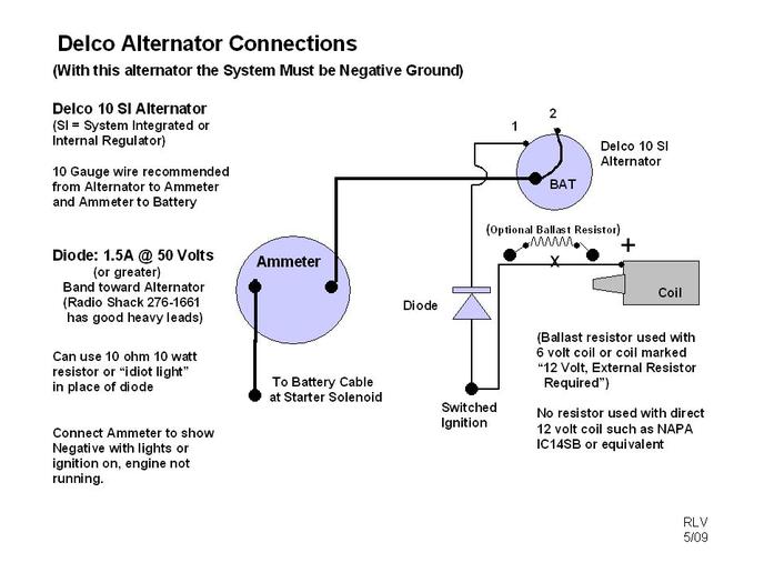
I picked up an alternator at a wrecking yard. It came off a GMC full sized Jimmy about 1980 vintage . It has three wires coming out of it. Can anyone send me a wiring diagram so I'll get it hooked up right? I would appreciate some help on this one. It is going on a Ferguson TO 35.. Thanks
- Thread starter AZ ANTICS
- Start date
Similar threads
We sell tractor parts! We have the parts you need to repair your tractor - the right parts. Our low prices and years of research make us your best choice when you need parts. Shop Online Today.
Copyright © 1997-2024 Yesterday's Tractor Co.
All Rights Reserved. Reproduction of any part of this website, including design and content, without written permission is strictly prohibited. Trade Marks and Trade Names contained and used in this Website are those of others, and are used in this Website in a descriptive sense to refer to the products of others. Use of this Web site constitutes acceptance of our User Agreement and Privacy Policy TRADEMARK DISCLAIMER: Tradenames and Trademarks referred to within Yesterday's Tractor Co. products and within the Yesterday's Tractor Co. websites are the property of their respective trademark holders. None of these trademark holders are affiliated with Yesterday's Tractor Co., our products, or our website nor are we sponsored by them. John Deere and its logos are the registered trademarks of the John Deere Corporation. Agco, Agco Allis, White, Massey Ferguson and their logos are the registered trademarks of AGCO Corporation. Case, Case-IH, Farmall, International Harvester, New Holland and their logos are registered trademarks of CNH Global N.V.
Yesterday's Tractors - Antique Tractor Headquarters
Website Accessibility Policy