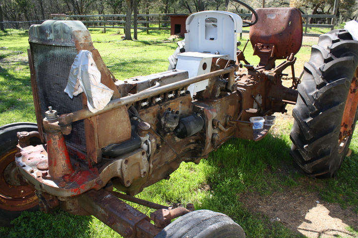
Picture 3 red marked pins. that lever moves when operating rod moves. Center pin pivot. Rear pin moves piston to close off bypass for pump pressure or open to sump. front pin moves the lever that lets unit out let pipe pressure back to sump. Notice 2 pins with yellow marks in front. One pin releases the check ball for the lt. rear opening and the other one releases the lt. front and right openings. Notice lever is made so one pin is pushed before the other. Hard to feel when operating with out a load on the check balls or a worn unit.
Picture of pump unit, oil comes in at the squared part and pressure out to the channel and over to the two silver balls. If the operating lever is pulled back pressure pushes the spring loaded balls in so pressure goes to the outlet ports. These are the same balls the pins push in to let oil back to the sump from the outlets. Ball with red mark near it goes to left front and right outlets. Yellow to left rear outlet.
Since both balls see the same pressure from the pump all the outlets have the same pressure. Unless a delay lift valve is used or when lift cylinders are used on a outlet and they are a different size or lifting a different load. Then the cylinder that needs the least pressure to lift will go to the end of travel before the next one lifts. If a gauge were put in all three blocked outlets on the unit and it was set to pump all would see the same pressure almost instantly.
Tried to make this short as I could so it may not be explained good enough, questions ask.


