alternator diode question

55 50 Ron

Well-known Member
Installed a new wiring harness on a Super MTA that had been converted to 12 volts negative ground.

The diode to pin 1 on the alternator had a 39 ohm, 5W resistor in series in the old harness. What is the purpose of this resistor? I haven't seen one like this before. Am wondering if I should put the resistor in with the new harness?
 
purpose of diode is so you can shut tractor off. Without diode or resister it will backfeed and keep running. I thought usually just diod or resister were used, not both. Perhaps reisster did not stop problem so they put diod in also.
 
The resistor is to prevent substantial current from flowing into the alternator from the ignition in the case that the alternator's internal regulator shorts out. It is a bit redundant in that the resistor alone will work to allow excitation. I have not seen any (nor heard of any) shorted to ground regulators that cause the issue above, so I don't recommend te use of both. But I have no issue with a marker lamp, diode, or resistor at or above 10 ohms being used to limit back feeding the ignition. Jim
 
Similar to the other gents, I use a 10 ohm safety current limiting voltage dropping resistor in the alternators external excitation circuit so the engine doesnt continue to run (via alternator backfeeding the coil) when the IGN switch is turned off. (talking about the GM 10SI 3 wire family of alternators that use external initial excitation voltage to start charging) A didoe serves the same purpose (has a 0.6 voltage drop) but doesnt provide the small degree of current limiting like a resistor does, which is why I use a resistor instead of a diode.

For another double duty method, you can instead use a small "incandescent" NOT LED indicator light which provides current limiting to prevent run on plus serves as an idiot light.

I think it was Bob M who noted you might even place a resistor in paralell with the idiot light so the alternator still excites even if the light were to burn out...

John T
 
I agree, a small bulb like a 194 is simple and cheap plus it is visual. I tuck mine in the hood space where the steering goes through,you can see it from the seat, but doesnt show otherwise and protected from the weather.
 
(quoted from post at 10:20:18 01/24/13) Similar to the other gents, I use a 10 ohm safety current limiting voltage dropping resistor in the alternators external excitation circuit so the engine doesnt continue to run (via alternator backfeeding the coil) when the IGN switch is turned off. (talking about the GM 10SI 3 wire family of alternators that use external initial excitation voltage to start charging) A didoe serves the same purpose (has a 0.6 voltage drop) but doesnt provide the small degree of current limiting like a resistor does, which is why I use a resistor instead of a diode.

For another double duty method, you can instead use a small "incandescent" NOT LED indicator light which provides current limiting to prevent run on plus serves as an idiot light.

I think it was Bob M who noted you might even place a resistor in paralell with the idiot light so the alternator still excites even if the light were to burn out...

John T

Actually this set up might be the best of both worlds.

The resistor will provide protection in case the battery to alternator wire becomes an open circuit which would cause the alternator output to all be on the #1 terminal circuit. The diode would provide a low resistance path to allow for a lower start up speed for the alternator.
 
(quoted from post at 03:39:05 01/25/13)

"Actually this set up might be the best of both worlds.

The resistor will provide protection in case the battery to alternator wire becomes an open circuit which would cause the alternator output to all be on the #1 terminal circuit. The diode would provide a low resistance path to allow for a lower start up speed for the alternator".

I am not following this: How are you connecting the diode and the resistor?

My understanding would be - if connected in series the diode cannot provide a low resistance path and if connected in parallel the resistor cannot limit current.
 
Ah! So that"s why my 340 runs on after shutoff, for a few seconds. I"ve wired the diode in series, but not the resistor. Anyone care to draw a short wiring diagram? Learn something new each day. Thanks!
 
Google " bob melville" for drawings.
I converted my H and used a Chrysler voltage dropping resistor to keep the 6v coil and dizzy the same. Just reverse the leads on the coil because It's now 12v neg gnd.
 
(quoted from post at 09:12:41 01/25/13) Google " bob melville" for drawings.
I converted my H and used a Chrysler voltage dropping resistor to keep the 6v coil and dizzy the same. Just reverse the leads on the coil because It's now 12v neg gnd.

The only thing needed to get rid of the risistor is a 12 volt coil. The points and condenser will be just fine. Dizzy stays the same. Only reason I kept the 6 volt coil on my M is I had the resistor and was low on funds at the time. Going with a 12 volt coil next tuneup.

Rick
 
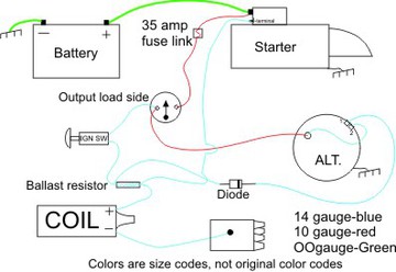
Ron, you need the diode or light bulb to keep the alternator from back feeding the ignition system as others have posted.

14116.jpg


The picture shows how to just wire a GM alternator. That wiring will not change with a new harness.

Rick
 
The voltage dropping resistor is a lot cheaper than the 12 volt coil,but I also thought that the condenser in the dizzy would need changed.
 
This should help. The Starter is from a large frame but your relay should be similar. Both should not be necessary if the diode is placed with the band end as shown. Jim
c51194.jpg
 
(quoted from post at 15:27:49 01/25/13) The voltage dropping resistor is a lot cheaper than the 12 volt coil,but I also thought that the condenser in the dizzy would need changed.

It is cheaper but I'm a student of the "keep it simple" school. Taking the resistor out just eleminates one more thing that could go wrong. 12 volt coil really isn't that expensive. Last one I got was around 25 bucks.

Rick
 
(quoted from post at 10:11:52 01/25/13)
(quoted from post at 03:39:05 01/25/13)

"Actually this set up might be the best of both worlds.

The resistor will provide protection in case the battery to alternator wire becomes an open circuit which would cause the alternator output to all be on the #1 terminal circuit. The diode would provide a low resistance path to allow for a lower start up speed for the alternator".

I am not following this: How are you connecting the diode and the resistor?

My understanding would be - if connected in series the diode cannot provide a low resistance path and if connected in parallel the resistor cannot limit current.

It is basically a solution in search of a problem that you are not likely to ever see. It really only applies if the alternator wire on the #2 terminal is connected remotely such as at the starter solenoid instead of the alternator output terminal. Connected remotely gives better control over the battery voltage than having it connected at the alternator.

Connect them in parallel.

When starting the diode will provide low resistance to energize the alternator. It will also prevent any current from flowing back to the switch which ensures that the switch can control the power to the coil.

The problem with having only a diode in the circuit to energize the alternator is if the wire between the alternator output and the battery should become open all the current would be fed through the #1 terminal back to the switch. With no path back to the sensing wire the alternator voltage will rise until it destroys the alternator. The resistor allows some of the current to flow back through the circuit so the sensing wire can still control the voltage but limit the current to prevent over loading the circuit.
 

We sell tractor parts! We have the parts you need to repair your tractor - the right parts. Our low prices and years of research make us your best choice when you need parts. Shop Online Today.

Back
Top