1971 Model 140 converting to alternator

Put a Hitachi 14231 or a Delco 10si (hitachi is smaller) on the tractor. With few changes the bracket will adapt easily. One 10ga wire to the amp meter from the output terminal, one 14ga wire from that terminal to the #2 (or S on the Hitachi), and one 14ga wire from terminal #1 (L on Hitachi) to a clearance light bulb then to the ignition switch side of the coil.
If using the original coil, use a 1966 chevrolet ballast resistor to drop the coil voltage to match the coil. (wire above goes to switch side of ballast). Change the polarity of the coil so negative goes to the distributor and positive goes to the ballast. If you change the coil, use a 12v no resistor needed to avoid the ballast resistor. If it was 12v to start with it may have the correct wiring on the coil except polarity. If 6v change the bulbs. The starter will be fine as is, it will spin correctly. Enjoy. Jim Diagrams can be found in the archives under Bob M diagrams. Jim
 
If the tractor already has a 6 Volt system on it you could go to a 6 volt alternator and not change anything.
 
I converted my 1966 140 (also 12V genny) just as Janicholson described in 2006. Trouble free since even running three Piper Cub landing light bulbs in the stock housings (upgraded wiring).
 
(quoted from post at 10:33:52 07/06/16) Easy is what I am after

I have the same set up and want to change to an alternator. What is required to do all of this. I can fix mechanical things but not so much with electrical.
mvphoto1290.jpg


mvphoto1291.jpg

[/img]
 
I converted my Super A this season, although was 6v pos ground originally.

I went to ebay and searched for "Denso mini 1 wire alternator" which are around $60. It came with a pulley.

After some measuring, I fabricated the mount in the shop.

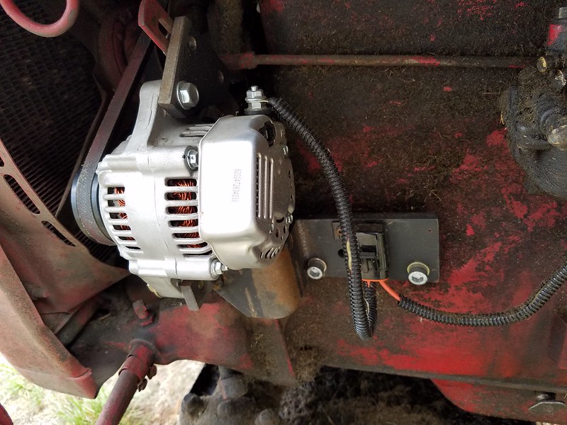
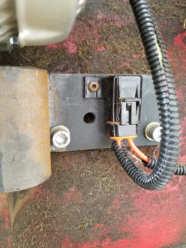
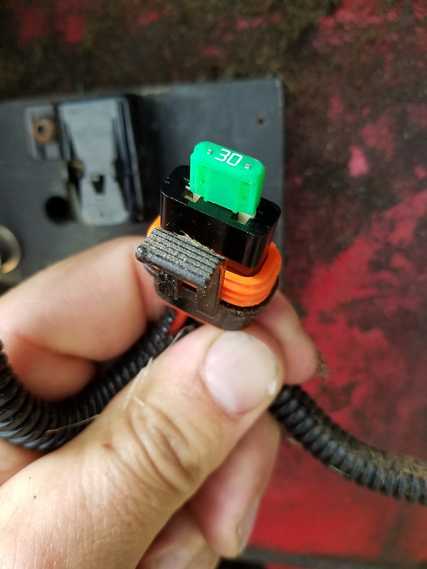
I put in a 30A weatherpacked fuse asm, between the alternator and the battery, also from ebay.

The voltage regulator was abandoned, and I built a complete new wiring harness. You can probably abandon the "Field" terminal on the generator and the voltage regulator.

I kept the ammeter, in series between the alternator and battery, it works just fine.

The mini alternator excites right away without revving the engine, anything but the extreme low idle speed. It appears to charge the battery back in about 5 minutes' time, as viewed from the charge/discharge state of the ammeter.

Overall I'm happy with it, very much smaller in diameter than the GM truck-style alternators. Really the only question left in my mind is if the alternator is validated to the same durability standard as the truck versions.
 
Here are a couple of pics


When I type "weatherpack" is not a genuine GM/Delco/Delphi part but has a similar triple lip silicone gasket just like the weatherpack vehicle wiring harness connectors. I tried to do the best job I could of using glue-laden heat-shrink butt splices from Panduit and the split conduit. The alternator bracket has a few rough edges and corners but it works pretty well. The 3 bolt bracket at the top allowed me to use the original adjuster slot without any more modifications.
 
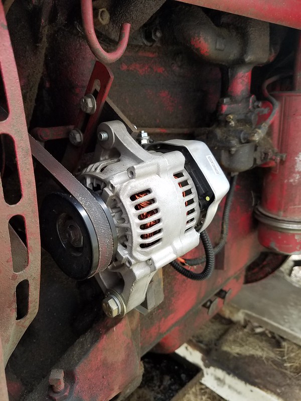
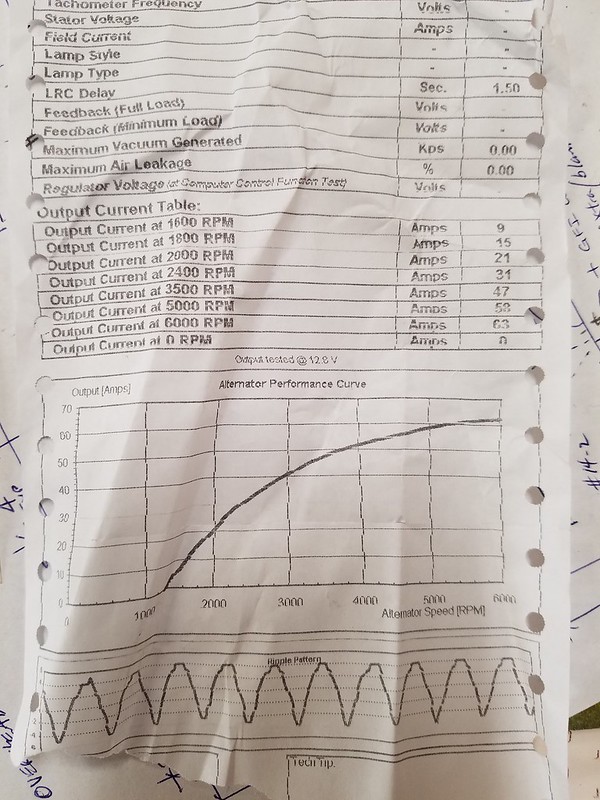
So is a 30 amp alternator big enough. I see on Steiner's they sell the 63amp for this

I couldn't see this post in Modern View but my opinion is this. If I remember correctly, the "~30A alternator" can give you 60A if you spin it up to like 7-8000rpms. I have a printed output curve that came with the mini alternator that's not with me at present, I can post it over the weekend. However no way am I going to overdrive it like that for just running the ignition and charging the battery. I don't mow at night: the only other draw other than the ignition would be continuous use of the headlights/taillights.

My other opinion is the one Steiner is selling for $149 is the exact same one that's ~$60 on ebay.
 
Here is the charging/ouput curve I posted about earlier. It shows 63A output at 6000rpms. I'm guessing it runs in the 2000-2500rpm range which is plenty for recharging the battery.

 
mattofvinings, you also said you built a new wiring harness. do you still have a schematic?
What gauge wires did you use?
 
Sure, here is my diagram.

A couple of notes. I used THHN stranded copper wiring, basically left over from industrial projects, its typically also rated THWN for "Wet" locations. I encased this in the split black conduit to prevent chafing or wear.

I went with 2 different 30A fuses. Reason is the way I wired it there is potentially a current path from alternator to battery when the engine is running, and also from the battery to the ignition depending on the state of charge or discharge.

I used a weatherpack relay for the ignition. I wanted to make sure that the ignition was receiving full voltage/full current and wasn't being "cheated" electrically speaking by any high resistance in the old start-stop switch. So the start stop switch now just handles milliamps to pull in the relay coil, the -(CR)- in the diagram. The normally open contact which is -][- in the diagram is the actual "heavy" current flow path. The relay is from ebay, its a Hella brand, with the weatherpack/gasketed base and sealed wires. One has to be careful and insulate the pigtail supplied for the normally closed contact, as that would be +12vdc at all times the tractor is off, so it could be a path to a short circuit/arc to ground if not insulated. The relay just fits in behind the control panel.

Any butt splice connections were made with Panduit heat-shrink "glue" butt splices, models BSH-10E (10-12awg) and BSH-14Q (14-16awg). The "hot melt glue" actually seals around the wire OD for an even better moisture seal, in addition to physically shrinking down.

I tried to keep the "feel" of the tractor as original as I could, obviously the weatherpack fuses aren't original, but the original ammeter works perfectly and the push-pull start-stop button is unchanged.

I currently have no working lights but could easily add this in the future, I would either need to wire the two 6v headlamps in series or invest in new 12v sealed beam units. I would just run another conductor down inside the alternator side of the split conduit. There may be more efficient ways to wire this, but that's what I went with at the time. I installed in late spring of this year and has been used weekly for mowing with no issues.

Please ask questions if you have them, I'd be happy to try to answer.
 
Hi, sorry, I see you asked twice.

I would put it just before the ignition I have listed on the diagram.

In other words, feed the 12v to one side of the resistor. In your picture that looks like the side with the yellow butt splice.

The other side would then be dropped down to 6vdc (+/-) and you can use this to feed the ignition coil. That's the voltage it would like to work at.

Being a resistor, it should work equally well both ways, so there's no worry about being on the "wrong" terminal. 12v in, and 6v out, no matter which way you wire.

I hope this answers your question.
 
(quoted from post at 09:41:00 08/22/17) Hi, sorry, I see you asked twice.

I would put it just before the ignition I have listed on the diagram.

In other words, feed the 12v to one side of the resistor. In your picture that looks like the side with the yellow butt splice.

The other side would then be dropped down to 6vdc (+/-) and you can use this to feed the ignition coil. That's the voltage it would like to work at.

Being a resistor, it should work equally well both ways, so there's no worry about being on the "wrong" terminal. 12v in, and 6v out, no matter which way you wire.

I hope this answers your question.

It does but makes more. So is this set up telling me I have a 6v ignition? I do have a 12v battery. If it is a 6v ignition then the resistor just drops down the voltage to 6v. I should have no issues then with this swap out to the 12v alternator?
 

Yes, seeing as you have a 12v battery, 12v gen or 12v alternator already, the presence of the resistor points to the original 6v coil being used.

My opinion is that changing alternators (I'm guessing you are going to the "Denso 1 wire mini") will not cause any effect on the way the ignition coil runs. Just keep the resistor in the same configuration as before to drop down the voltage.

On my particular tractor I am running a 12v ignition which doesn't need the resistor, so that's why I don't have it in my wiring diagram.
 
So I started the project last night. I purchased a bracket from Steiners
mvphoto2417.jpg

and used the mini alternator.
Ran into a problem, the pulleys don't line up, there is about a 1 inch difference in them lining up. The bracket is slid all the way forward and the alternator is also
Wondering if it is because of the mini alternator? If I go with a full size alternator will they line up? The bracket is for my tractor and is says it is for this alternator
mvphoto2418.jpg

Hate to pay 100 for something that I could get at NAPA or an auto store cheaper.
What would be an equivalent alternator at napa or wherever to get? I know I don't need that many amps either.
 

I don't know why my last post did not show up here but here is the link to my topic/questions
http://www.yesterdaystractors.com/cgi-bin/viewit.cgi?bd=farmall&th=1049164


I don't know why my last post did not show up here but here is the link to my topic/questions
http://www.yesterdaystractors.com/cgi-bin/viewit.cgi?bd=farmall&th=1049164
 
(quoted from post at 05:09:34 08/22/17)
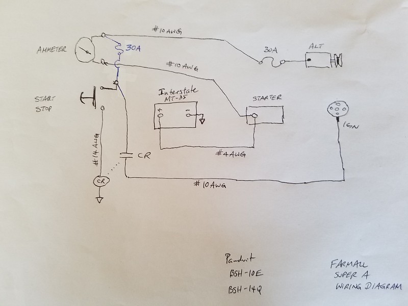
(quoted from post at 22:14:15 08/09/17) Here is the updated wiring diagram.

mvphoto2373.jpg


How do I work this resistor into the wiring diagram?

So I have it wired up but the alt is not charging. Had it bench checked and it works. Can a bad ammeter cause this? Had it running and checked the voltmeter on the battery and only 12 volts. Looks all to be same except for the coil relay. I'd o t have one and not sure what it even looks like. Revd up the rpms still no charge
 

So I have a one wire alternator.
I have a wire from the alternator to the ammeter with a 30amp fuze in that line.
From that same post on the ammeter I have a wire that goes to the on/off switch with a 30amp fuze in that line.
The other post on the ammeter I have a wire that goes to the starter.
The other post on the on/off switch goes to the ignition.

The on/off switch works but if I remove the neg cable from the battery it dies.
I pulled the fuze from the alternator line and checked it for volts and only 5.4.
I am guessing that it is not getting excited?
I have it a full rpms but still not putting out enough to charge the battery.
What am I missing?
 
Imo, you should be able to just measure battery (+) to battery (-) to check the alternator function, rather than pulling the fuse out.

It should get around 14vdc with the alternator charging. Should be around 12vdc in a resting/engine-off or discharge-state with engine running but ignition as the only electrical load.

I have another Denso-mini I put on the SMTA and I'm going to try it this week as a 3-wire (it has the other two terminals on the back side for the I-ignition and L-lamp) although I plan to use a diode to prevent blowing out the field's diodes inside the voltage regulator. In this case, it does not charge at low idle but will charge when revved to "medium" rpms...as viewed from the standard factory ammeter. I would like it to charge/regulate at idle. The one on the SA in 1-wire configuration starts charging almost immediately...not sure why the difference.
 
I did do that on the battery and it was about 12v. I decided to check at the fuze to see what the output of the alternator was.
 
The bracket I purchased I was not able to use the mini so I got a full sized alternator.

Just need to know how I can get it to excite.

I have read about putting a light or a diode in there but have no idea where or what.
 
Here's a good article.

The way I understand it is this. By supplying 12vdc (switched from ign or from B+) to the "I" or IGN (I think its the "2" term on a 10si) you supply electrical energy to excite the magnetism in the alternator's field, independently of it having to do that internally, as would be the case in a 1 wire setup.

A bulb is commonly shown on the "L" or "lamp" terminal, (I think its the "1" term on a 10si). This also has 12vdc fed to the alternator via ign switch. A resistor can be used in place, or a diode can be even cheaper. I have some 1N5408 diodes, these are wired with the band on the terminal closest to the alternator. This part of the circuit is for "monitoring". If the connection from the main output lug of the alternator back to the battery (B+) is compromised, without resistance or current limiting in place, the alternator output will smoke the internal field diode triad without the "high power diode triad" being able to operate normally and "process" this power output.

The monitoring bulb would be something like 14.x vdc pushing 12vdc so a 2vdc potential difference to operate the bulb. With a resistor or diode there is no visual indication, but at least the circuit protection for the field is in place.

This is also why its a poor idea to pull off connections and fuses while the alternator is turning. With the main, expected current path interrupted, it can attempt to exit thru the field.

There is another post which I cant find right now which illustrates this beautifully with wiring diagrams. I'm just paraphrasing in english. If I find it I will post it as a followup.
 
(quoted from post at 18:44:54 09/11/17) The article I forgot to link
http://www.yesterdaystractors.com/articles/artint195.htm

The other post I found via "images"...
http://www.yesterdaystractors.com/cgi-bin/viewit.cgi?bd=ttalk&th=1055039

All good reading to understand this better.

So I have it all wired up with a 194 bulb.

The bulb stays on all the time. I have it wired up as the diagrams state with terminal one going to the light then to the ignition switch(black wire) and terminal two going to the BATT on the alternator.

meter on battery when running is around 12v.
Ran up RPMs just in case.
Alternator was bench tested prior to purchase

Any idea why the light would stay on?

mvphoto3962.jpg


mvphoto3963.jpg
 

We sell tractor parts! We have the parts you need to repair your tractor - the right parts. Our low prices and years of research make us your best choice when you need parts. Shop Online Today.

Back
Top