12 Volt Alternator with Magneto Diagram

Ken Christopherson

Well-known Member
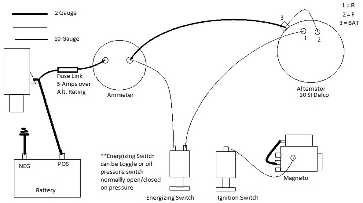
Hello all.. I made this diagram going off of some research I did and found a post by Janicholson about 6 years ago. This is for those who wish to retain their magneto, yet run a 12 volt electrical system otherwise. I hope it helps you all. Looking forward to doing this conversion myself. For the "energizing switch" I was planning on using a 2-pole ignition switch (push/pull) like you can purchase from this site to match the original ignition switch. That way, I will have a single pole switch for the mag, and a matching double-pole switch for the charging system. Oil pressure switches can also be "tee'd" into the oil pressure line if needed.

If anyone sees any issues, please let me know and I will fix it. Again, I tried to do the best I could going off of Janicholson's post some years back. Plan on doing this to my M, H, Case SC, and JD A.
a151969.jpg
 
The 1=R 2=F 3=Bat list should be 1= energizing circuit, 2 = voltage sensing input, 3= Alt output.
THe amp gauge needs to be capable of the alt amp output. Some alternators put out enough to burn out the amp gauge before the fuse link. The energizing switch can be a momentary contact push button (it will keep the alt from staying "ON" if the operator might forget to turn off the toggle. Jim
 
Good info! Thanks Jim! I'm no electrical guru - I was just going off of your diagram that you posted years ago, and figured I would try to doctor it up a little bit for my own needs.. Then I though, heck.. Might as well post it!
 
Nice and clean. add a bit as noted, and pit it in Parts and pieces to the left. maybe 10SI with Mag Diagram Jim
 
Thanks for putting up the diagram!

Curious if the original rotary light switch can be retained and functional with a 12V conversion?

I've never actually seen my tractor run, let alone use the switch, but doesn't it also control the charge rate of the generator?
 
It depends on the switch, I think? 3 Position switches are "Off-Dim-Bright", whereas the 4 position are Low charge/high charge/dim/bright If I am correct. Again, I am no electrical guru. Maybe Janicholson can chime in on this one?
 
A three position switch does not control the charge rate. a 4 position switch does have that ability if used with a cutout relay only (no voltage regulator). It can't be used for the alt control because its function in the original circuit was to ground the field of the generator to make it charge. Thus it is a ground source not voltage source. Jim
 
A double point/double throw toggle switch works. That is what i put on my M. Works great. Used it to day.

Bass
53superC
 
IMHO, the oil pressure switch is the way to go. It makes the system a lot more "idiot proof" if anyone but you will ever start and run the tractor.
 
This long article will explain where best place is to hook up remote sense wire.
They way you wired it, alternator thinks it is a one wire alternator as far a sensing
voltage needs. If you are installing an alternator why not have it work as good as it can?

http://www.madelectrical.com/electricaltech/remotevoltagesensing.shtml
 

Here is a picture of the oil pressure switch kit that I put together for installing an alternator kit on a tractor that is equipped with a magneto.
45864.jpg
 

We sell tractor parts! We have the parts you need to repair your tractor - the right parts. Our low prices and years of research make us your best choice when you need parts. Shop Online Today.

Back
Top