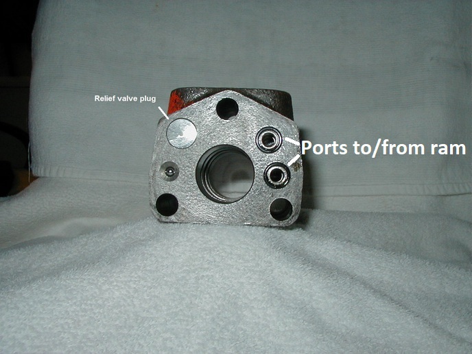
I can address this cylinder only as it is mounted on Case wheel tractors. I don't know if you have the identical cylinder on your forklift, that is something you will have to determine by these pics.
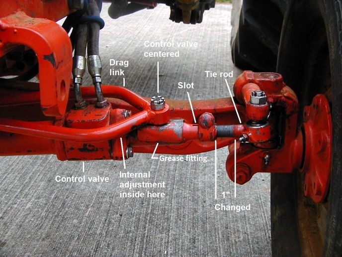
First some questions, did you have equal wheel swing in both directions before the seals replacement? Are your tie rods adjusted to have the wheels straight ahead when the piston spool is in mid travel in the cylinder control valve? In other words the drag link is not holding the spool out of neutral.
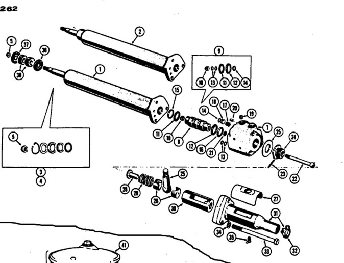
Pull the grease fitting #35 at the bottom of the valve actuator and see if that makes any difference. The original zerk had a very short thread and most modern zerks are threaded longer and can bind the actuator #30. Check that the tie rod is turned into the outer sleeve 3 full turns showing in the slot (disregard 1? setting in my pic).
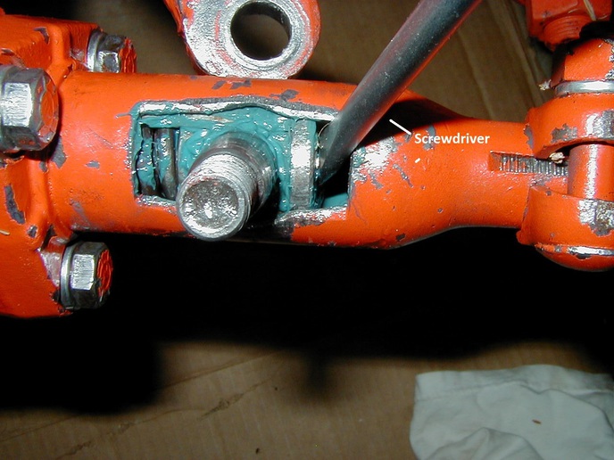
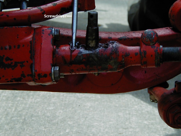
When the dust cover is on the valve actuator and you're stroking with the drag link it is very difficult to determine that the valve spool is fully stroked. Spool travel is very narrow, less than a 1/4" total so it doesn't take much to cause problems. Pull the drag link & dust cover off. Jack the wheels off the ground, engine running, stroke the actuator both ways with a screwdriver. If the wheels move both right & left equally, the valve spool or actuator may be binding and the drag link is just leaning the ball stud rather than fully stroking the valve spool.
If the valve spool strokes fully in one direction and very little in the other, adjuster nut #24 is not set right and/or pin #23 may have been broken when assembling, obstructing spool movement.
If the valve spool seems to be stroking near equally in both directions but wheel swing is unequal, you can change the position of the adjustment nut #24 to center the spool in the valve body. I don?t remember which direction to turn the nut relative to wheel swing. My 310 adjusting nut is up tight and backed off between ? & ? turn. This is a often a tedious, messy job due to individual cylinder slop and wear. Careful with pin #23 on reassembly, it is easily broken and will obstruct spool movement in one direction, use heavy grease to hold in position while bolting up.
I would verify the pump pressure before trying to adjust the valve spool travel.
Joe
First some questions, did you have equal wheel swing in both directions before the seals replacement? Are your tie rods adjusted to have the wheels straight ahead when the piston spool is in mid travel in the cylinder control valve? In other words the drag link is not holding the spool out of neutral.
Pull the grease fitting #35 at the bottom of the valve actuator and see if that makes any difference. The original zerk had a very short thread and most modern zerks are threaded longer and can bind the actuator #30. Check that the tie rod is turned into the outer sleeve 3 full turns showing in the slot (disregard 1? setting in my pic).
When the dust cover is on the valve actuator and you're stroking with the drag link it is very difficult to determine that the valve spool is fully stroked. Spool travel is very narrow, less than a 1/4" total so it doesn't take much to cause problems. Pull the drag link & dust cover off. Jack the wheels off the ground, engine running, stroke the actuator both ways with a screwdriver. If the wheels move both right & left equally, the valve spool or actuator may be binding and the drag link is just leaning the ball stud rather than fully stroking the valve spool.
If the valve spool strokes fully in one direction and very little in the other, adjuster nut #24 is not set right and/or pin #23 may have been broken when assembling, obstructing spool movement.
If the valve spool seems to be stroking near equally in both directions but wheel swing is unequal, you can change the position of the adjustment nut #24 to center the spool in the valve body. I don?t remember which direction to turn the nut relative to wheel swing. My 310 adjusting nut is up tight and backed off between ? & ? turn. This is a often a tedious, messy job due to individual cylinder slop and wear. Careful with pin #23 on reassembly, it is easily broken and will obstruct spool movement in one direction, use heavy grease to hold in position while bolting up.
I would verify the pump pressure before trying to adjust the valve spool travel.
Joe