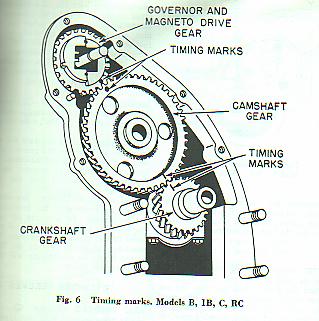
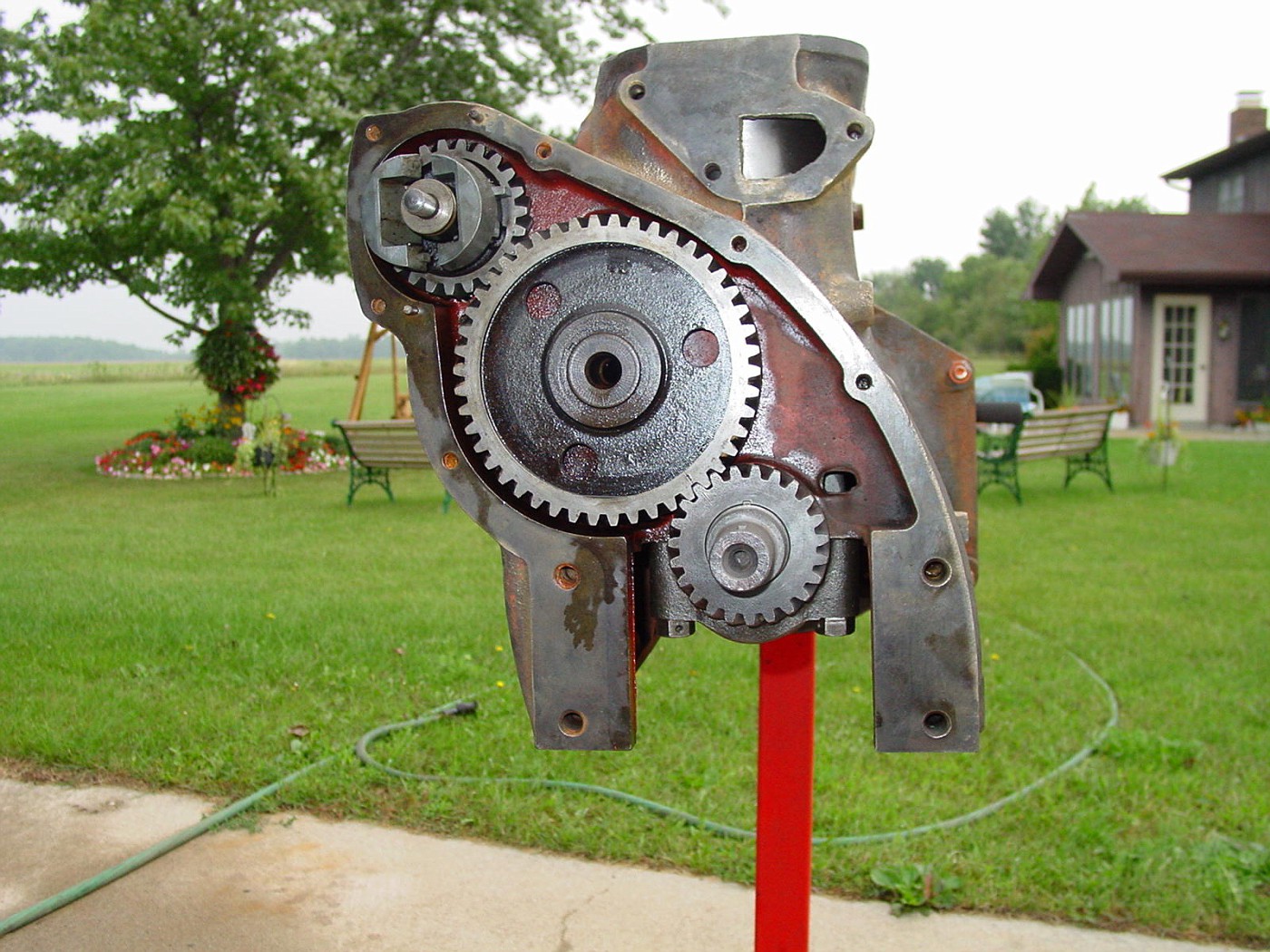
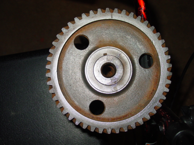
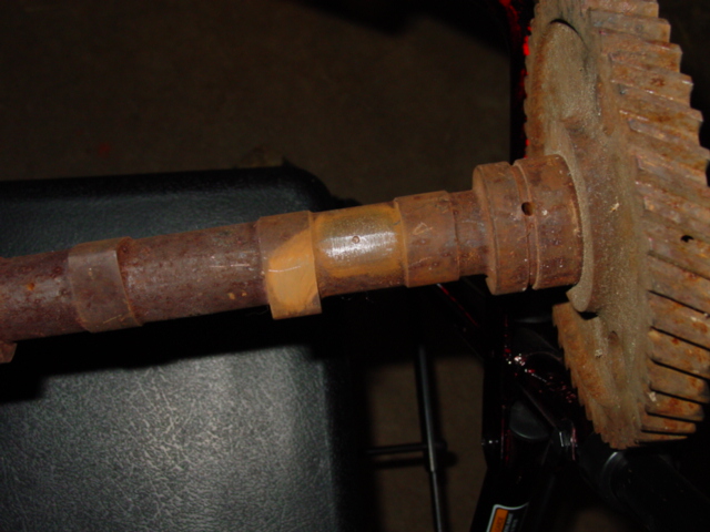
I have a 1953 B that is in process of being restored after sitting uncovered for years. As a result the cam was pitted beyond use. I acquired a good cam with gear that looks better than the original, less pitting on gear teeth. My question is that the two gears have timing marks in different places. I understand that the older gears had two straight marks versus a line and a circle on the later gears, but this older gear has the straight lines offset from where the marks are on the newer gear as well as punch marks offset from the lines. One punch at the governor mark, but offset one tooth from the same tooth as the newer gear based on the shaft key position (black circle in picture). There are two punch marks at the crankshaft timing mark in between the gear line mark and same space as the newer gear based on shaft key position (black line in picture). I could understand it if the factory marks were in the wrong position and someone punched new locations, but the punch marks are not offset in the same direction, one is offset CW and the other CCW. Any help explaining this would be appreciated.
Tony
[/img]
Tony
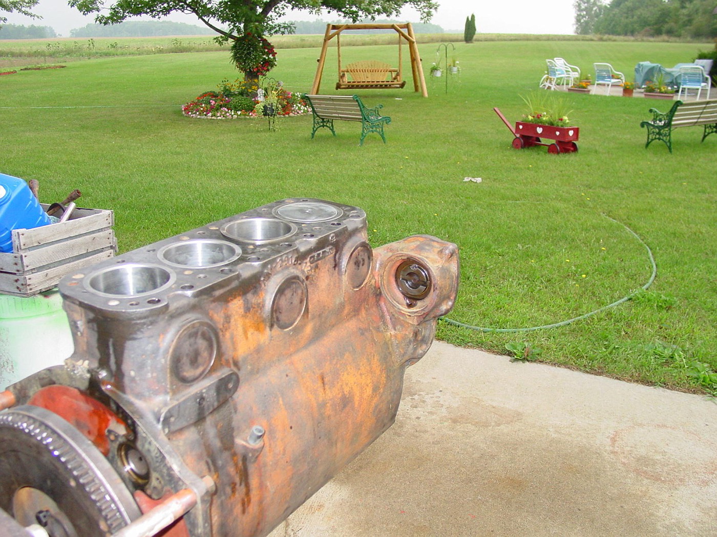
[/img]